Easidew Online User’s Manual
8 97094 Issue 18.5, March 2016
INSTALLATION
Item Description
1
°Fdp
When illuminated, this LED indicates that the displayed dew-point reading is in degrees
Fahrenheit.
Note: If neither the °Fdp or °Cdp LED is lit, ppm
V
is selected.
2
°Cdp
When illuminated, this LED indicates that the displayed dew-point reading is in degrees
Celsius.
Note: if neither the °Cdp nor °Fdp LED is lit, ppm
V
is selected.
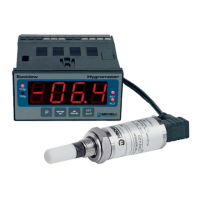
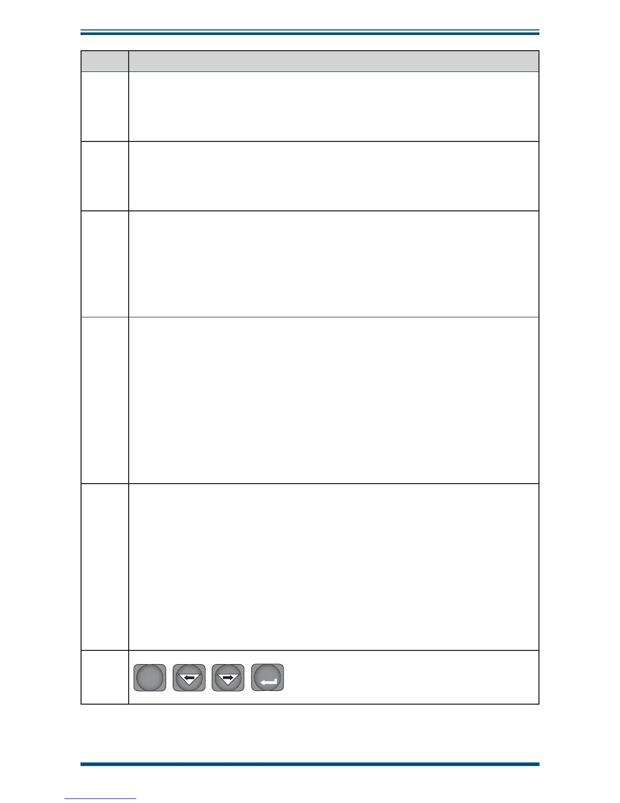
3
Main dew-point temperature display
Flashes to alternately indicate ErrL (error low) and temperature reading for low
temperatures under-range (lower than -100°Cdp (-148°Fdp) or -129.9°Cdp (199.9°Fdp)
for an open loop condition).
Flashes to alternately indicate
ErrH (error high) and temperature reading for high
temperature over-range.
4
AL1
When illuminated, this LED indicates that the dew-point temperature programmed
for Alarm 1 has exceeded the programmed threshold. Under these conditions the
alarm relay contacts associated with this alarm (normally open) will change state
(close) and will remain closed until the dew-point temperature moves back within
the programmed operational limit.
Alarm 1 is usually allocated to the Low alarm setting.
These relay contacts are rated at 250 V, 3 A and are connected as shown in Section 2.13.
Section 3.3.3 describes the setting up of AL1 trip points.
5
AL2
When illuminated this LED indicates that the dew-point temperature programmed for
Alarm 2 has exceeded the programmed threshold. Under these conditions the alarm
relay changeover contacts associated with this alarm will change state and will remain in
this state until the temperature moves back to within the programmed operational limit.
Alarm 2 is usually allocated to the High alarm setting.
These changeover relay contacts are rated at 250 V, 5 A and are connected as shown
in Section 2.13.
Section 3.3.3 details the setting up of AL2 trip points.
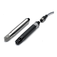
6
P
SET
The four function keys are used for setting up the
monitor.
Table 2 describes the operation of the keys.
Table 1 Monitor Front Panel Controls and Indicators