Easidew Online User’s Manual
24 97094 Issue 18.5, March 2016
INSTALLATION
Re-transmission Output
The re-transmission output is current sourcing. Connect the positive output to terminal
14 and the negative output to terminal 13. Use appropriately colored wires eg, red
(positive), black (negative).
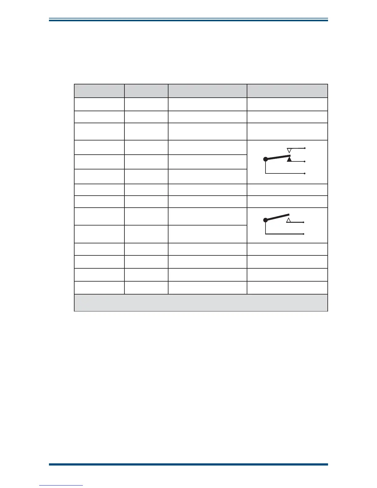
Terminal Wire Color Signal Supply Information
1 Blue 0 V (GND)
3 Green 4-20 mA loop current Default 4-20 mA
4Red
Transmitter loop supply
(+ve)
+24 V DC w.r.t. terminal 1
7 User defi ned ALR2 (normally closed)
9
7
8
8 User defi ned ALR2 (normally open)
9 User defi ned ALR2 (common)
13 User defi ned Current loop out (-ve) Default 4-20 mA
14 User defi ned Current loop out (+ve) Default 4-20 mA
16 User defi ned ALR1 (common)
16
17
17 User defi ned ALR1 (normally open)
23 (AC Version) Blue Power in (neutral) 100 – 240 V, 50/60 Hz
24 (AC Version) Brown Power in (live) 100 – 240 V, 50/60 Hz
23 (DC Version) Blue Negative (-) 0 V
24 (DC Version) Brown Positive (+) 24 V
NOTE: There are no terminals in positions
5, 6, 10, 11, 12, 15, 18, 19, 20, 21 and 22
Table 3 Summary of Electrical Connections