Easidew Online User’s Manual
18 97094 Issue 18.5, March 2016
INSTALLATION
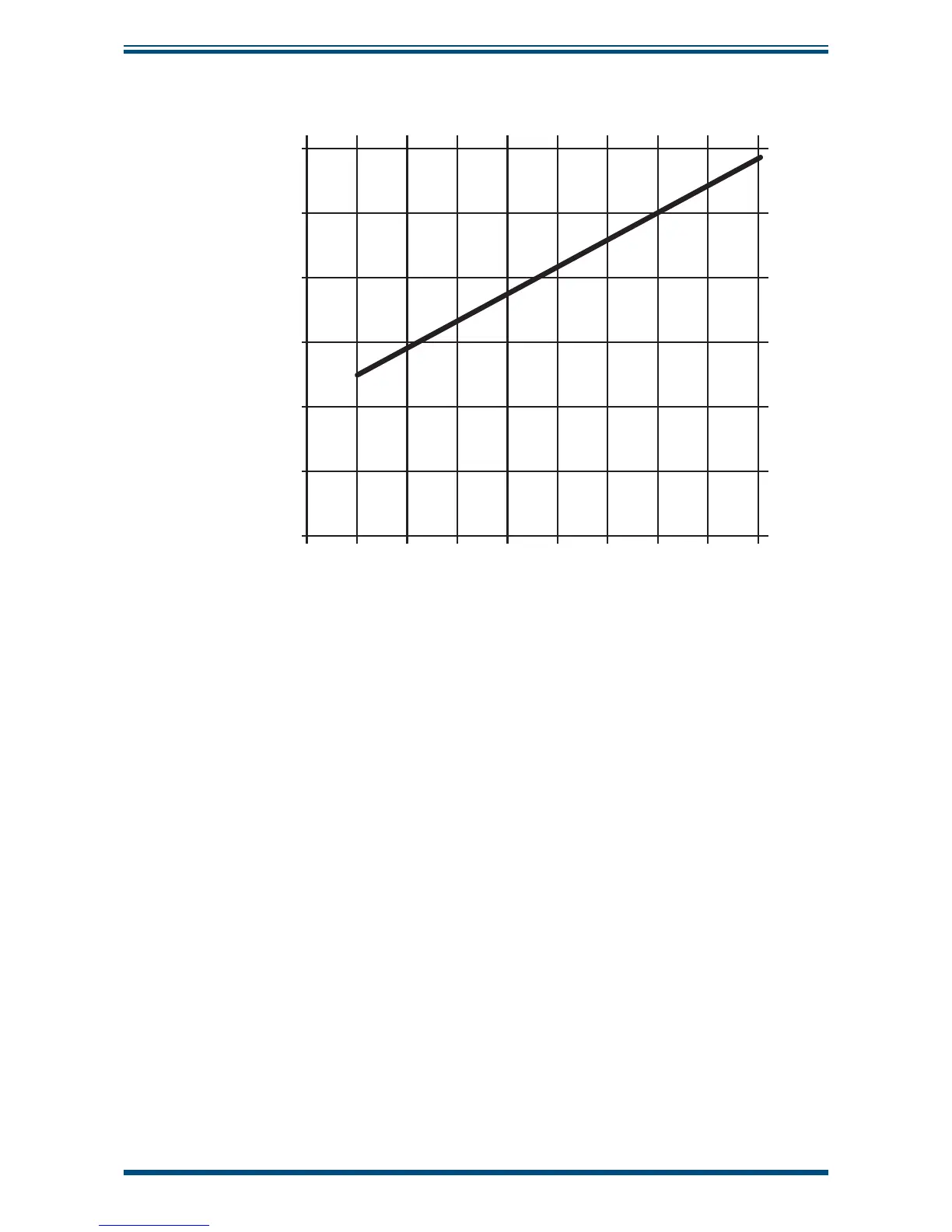
2.12.1 Electrical Boundaries
100
200
300
400
500
600
12 14 16 18 20 22 24 26 28
Resistance (ohms)
Supply Voltage
Figure 17
Maximum Load of Easidew - Including Cable Resistance
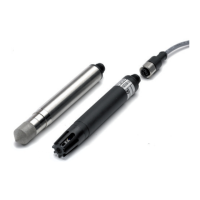
2.13 Transmitter Mounting
Prior to installation of the transmitter, unscrew and remove the blue plastic cover and
retain for future use. Take care to prevent any contamination of the sensor before
installation (handle the transmitter by the main body only, avoiding contact with the
sensor guard).
The Easidew can be mounted into either a fl ow-through sensor sampling block (optional)
or directly inserted into a pipe or duct and can be operated at pressures of up to 45 MPa
(450 barg / 6500 psig) when fi tted with the bonded seal provided.
The recommended gas fl ow rate, when mounted in the optional sampling block, is 1 to
5 Nl/min (2.1 to 10.6 scfh). However, for direct insertion applications, gas fl ow can be
from static to 10 m/sec (32.8 fps).
NOTE: Pass the bonded seal over the 5/8”- 18 UNF mounting thread and
assemble into the sampling location by hand using the wrench fl ats only. DO
NOT grip and twist the sensor cover when installing the sensor.
When installed, fully tighten using a wrench until the seal is fully compressed and to the
following torque setting:
5/8” - 18 UNF 30.5 Nm (22.5 ft-lbs)