Easidew Online User’s Manual
Michell Instruments v
3.4.2 Span and Unit Settings ............................................................................... 33
3.4.3 Alarm Set-Point Limit Confi guration .............................................................. 34
3.4.4 Scale Units to ppm
V
Set-Up .......................................................................... 35
3.4.5 Monitor Limits When Unit Scaled to ppm
V
.................................................... 36
3.5 Digital Communication Parameters Set-Up .......................................................... 37
3.6 Monitor – Reading the Displayed Value Using Modbus RTU Over RS232 ................ 39
4 GOOD MEASUREMENT PRACTICE .....................................................................40
4.1 General Operational Guidelines ......................................................................... 41
4.2 Maintenance and Calibration ............................................................................ 42
4.2.1 Clean Monitor ............................................................................................ 42
4.3 Fault Conditions ............................................................................................... 43
Figures
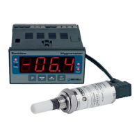
Figure 1 Easidew Online Monitor and Transmitter .......................................................1
Figure 2 Unpacking Method ......................................................................................3
Figure 3 Transmitter Unpacking Method ....................................................................4
Figure 4 Monitor Unpacking Method ..........................................................................4
Figure 5 Accessories Pack ........................................................................................5
Figure 6 Easidew Online Components .......................................................................5
Figure 7 Easidew Transmitter ...................................................................................6
Figure 8 Monitor Panel Layout ..................................................................................7
Figure 9 Mounting the Monitor ...............................................................................10
Figure 10 AC Power Supply Connections ...................................................................12
Figure 11 DC Power Supply Connections ...................................................................13
Figure 12 Sample Block Gas Connections ..................................................................15
Figure 13 Connector Terminal Block Removal ............................................................16
Figure 14 Wiring Connections ...................................................................................16
Figure 15 Connector Installation ...............................................................................17
Figure 16 2-Wire Connection Diagram .......................................................................17
Figure 17 Maximum Load of Easidew - Including Cable Resistance ..............................18
Figure 18 Transmitter Mounting - Sensor Block ..........................................................19
Figure 19 Transmitter Mounting - Pipe or Duct...........................................................20
Figure 20 Transmitter Mounting with Adapter ...........................................................21
Figure 21 Transmitter Connections............................................................................22
Figure 22 Monitor Rear Panel Connections ................................................................23
Figure 23 Typical Display .........................................................................................26
Figure 24 Change Alarm Switching Logic ...................................................................29
Figure 25 Set-up Alarm Levels ..................................................................................30
Figure 26 Confi gure Analog Output ...........................................................................31
Figure 27 Span and Unit Settings .............................................................................33
Figure 28 Set-up Alarm Set-Point Limits ....................................................................34
Figure 29 Set-up Monitor (to read ppm
V
) ...................................................................36
Figure 30 Set-up Data Communications Parameters ...................................................38
Figure 31 Installation Location .................................................................................41
Figure 32 Indication of Dead Space ..........................................................................41
Figure 33 Dimensions .............................................................................................47
Figure 34 RS232 Connections ...................................................................................49