Easidew PRO XP User’s Manual
2 97442 Issue 5, May 2018
INSTALLATION
2 INSTALLATION
2.1 Unpacking the Instrument
On delivery, please check that all the following standard components are present in the
packing box:
• Easidew PRO XP Transmitter (EX1 - Non-display OR EX2 - Display)
• Certifi cate of calibration
• 2 off bootlace ferrules
• 1.5mm A/F allen key (aluminium housing version only)
• 2mm A/F allen key (stainless steel housing version only)
• 1 off conduit entry blanking plug (fi tted hand tight)
• User’s manual
• Installation and maintenance information sheet
• Sample block (optional)
• Pipe mounting bracket (optional)
• EN10204 3.1 material certifi cates (optional)
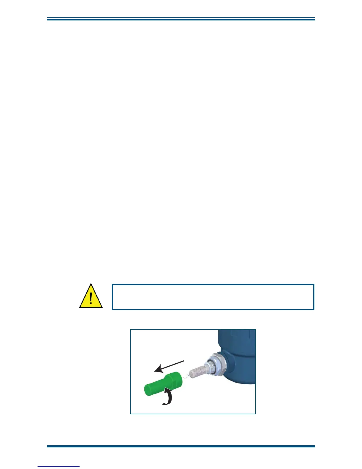
The Easidew PRO XP is protected within the main packaging with a green cap protecting
the sensor guard with a desiccant capsule inside, and a plastic cap inside the cable
entry opening (see
Figure 1).
Remove and retain these items prior to commissioning.
DO NOT HANDLE THE SENSOR GUARD
Figure 1
Sensor Cap Removal