Easidew PRO XP User’s Manual
16 97442 Issue 5, May 2018
INSTALLATION
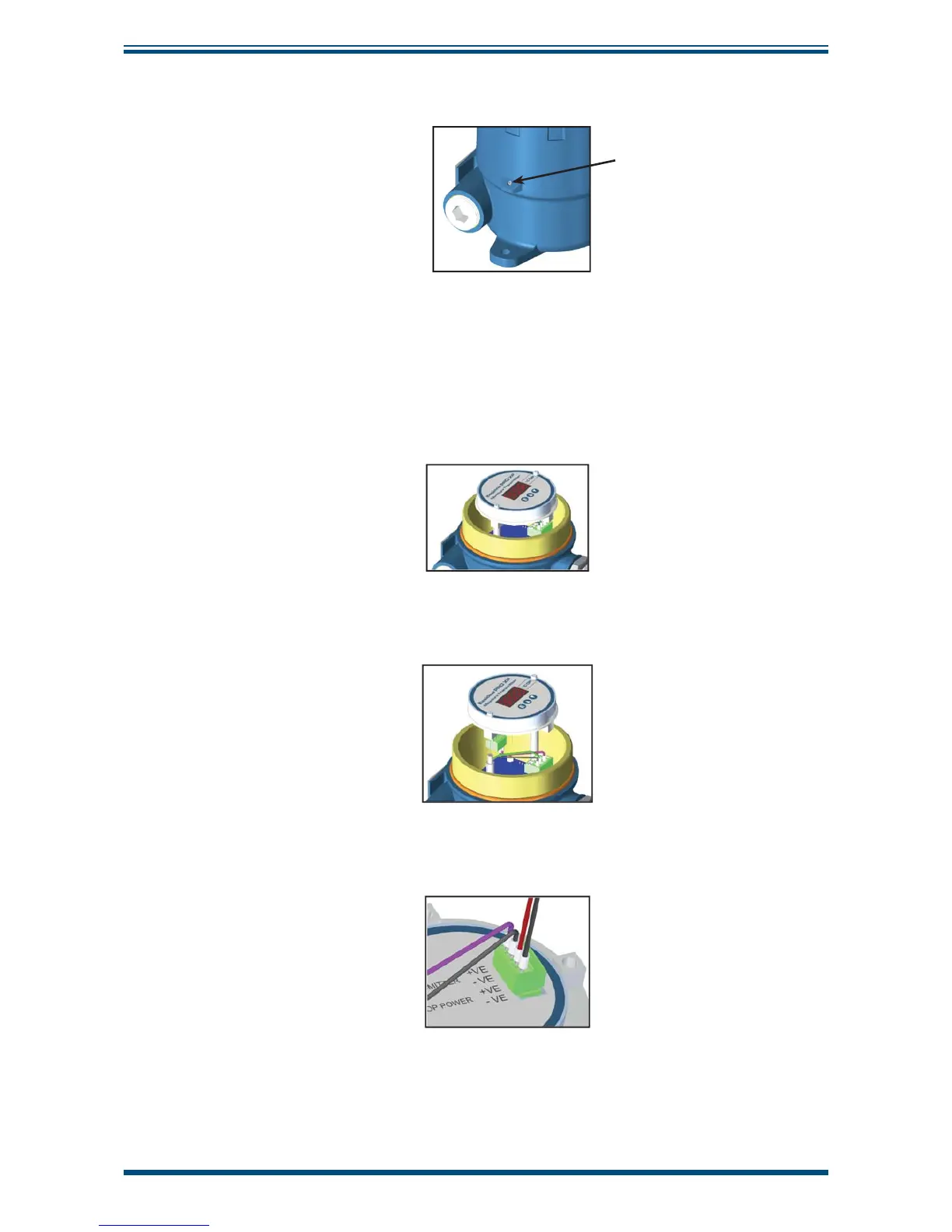
5. Re-fi t the enclosure lid in a clockwise direction until it stops and secure in
place by tightening the grub screw with a 1.5mm (0.06”) A/F Allen key.
Grub screw
Figure 16
Grub Screw
2.8.2 Terminal Block Connection - Easidew PRO XP EX2 (Display)
1. Remove the enclosure lid by carefully unscrewing anti-clockwise.
2. Lift off the display meter and integral mounting bracket from the 2
mounting posts and disconnect the terminal block connector from the
underside.
3. Mount each of the power and return wires into positions Loop Power +VE and
Loop Power -VE as shown, and tighten with a fl at bladed screwdriver (min
torque 0.25Nm (0.2 lbf-ft)).
Figure 17
Terminal Block Mounting - Easidew PRO XP EX2 (Display)