Easidew PRO XP User’s Manual
8 97442 Issue 5, May 2018
INSTALLATION
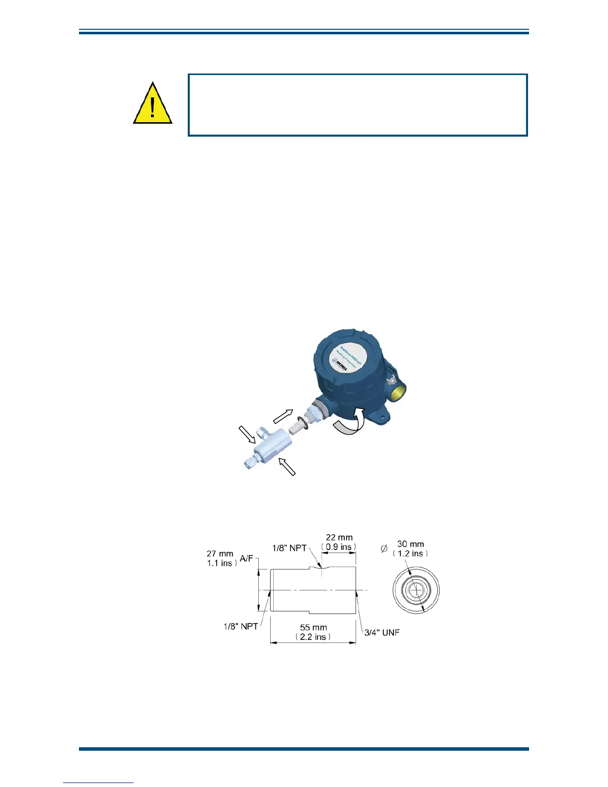
2.3.1 Sample Block (Optional)
The following procedure must be carried out by a qualifi ed
engineer to ensure the safe operation of the pressure system.
1. Remove the green protective cap and desiccant capsule.
2. Ensure the O-ring (see
Figure 8)
is located correctly within the O-ring
groove of the process connection and there is no contamination or debris
on its exposed surfaces.
3. Screw the transmitter into the sample block and, whilst holding the fl ats
on the block, tighten the seal nut to 40Nm (29.5 lbf-ft) to compress the
O-ring.
4. Rotate the enclosure to the desired position (up to 360° available) and
tighten the large clamping nut (32mm 1¼”) to 10Nm (7.4 lbf-ft) to ensure
dowty seal is correctly compressed for environmental protection (see
Appendix B.1).