Easidew PRO XP User’s Manual
18 97442 Issue 5, May 2018
INSTALLATION
3 OPERATION
3.1 Measurement and Confi guration
The Easidew PRO XP can be confi gured to provide an output of 4-20 mA (2-wire
connection) for the following:
Dew point -110 to +20°C (-166 to +68°Fdp)
Moisture content in gas 0 - 3000 ppm
V
(and equivalent mg/m
3
, lbs/MMSCF)
Moisture content in liquids 0 - 3000 ppm
W
The Easidew PRO XP is factory confi gured either as °Cdp (default) or °Fdp (North
America). The Easidew PRO XP can be re-confi gured by the customer, using the Easidew
XP Communications Kit (XP-CK) and Easidew Application Software. The Easidew
Communications Kit can be purchased from Michell Instruments or a local representative.
For a free copy of the Application Software contact Michell Instruments’ UK offi ce (see
www.michell.com for details of Michell’s contact information).
For moisture content in gas, the calculation from the measured dew point is assumed to
be at atmospheric pressure. Alternatively, a fi xed gas pressure needs to be programmed
into the Easidew PRO XP.
For moisture content measurement in liquid, the Easidew PRO XP requires the saturation
constant of the liquid to be programmed into the transmitters, either at the factory or
by the customer using the Application Software.
The transmitter requires a 6-point look-up table for saturation constants up to 3000
ppm
W
over the temperature range 0 to +50°C (+32 to +122°F). Saturation constants
for 8 common liquids can be programmed into the Easidew PRO XP via the Application
Software. Alternatively, the user can program saturation constants manually. The
Application Software Help fi le provides detailed instructions on how to perform this task.
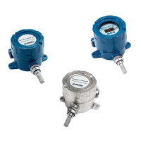
Easidew PRO XP EX2 (Display) Only
The display meter is simple in design and is a slave display to the measurement and
confi guration of the main transmitter pcb. It can be scaled linearly equating to the
circulating 4-20 mA signal output from the main transmitter pcb.
In order to re-confi gure the display, the enclosure lid should be removed by unscrewing
it in an anti-clockwise direction.
Care should be taken when unscrewing and replacing the
enclosure lid as the threads form an important part of the Ex
compliance regulations and therefore must not be damaged.
The lid must be replaced after using the display meter and the
grub screw tightened.
A full explanation of the operation and confi guration of the integral display meter is
detailed in Appendix D.