Easidew PRO XP User’s Manual
14 97442 Issue 5, May 2018
INSTALLATION
2.7.2 Easidew PRO XP EX2 (Display)
NOTE: To ensure compliance with EMC standards, ensure that the screen of the
power supply/signal cable or the power supply/signal conduit is connected
to ground.
With the cable entry option, a conductive cable entry gland is recommended,
allowing the transmitter housing to be earthed via the cable screen connection.
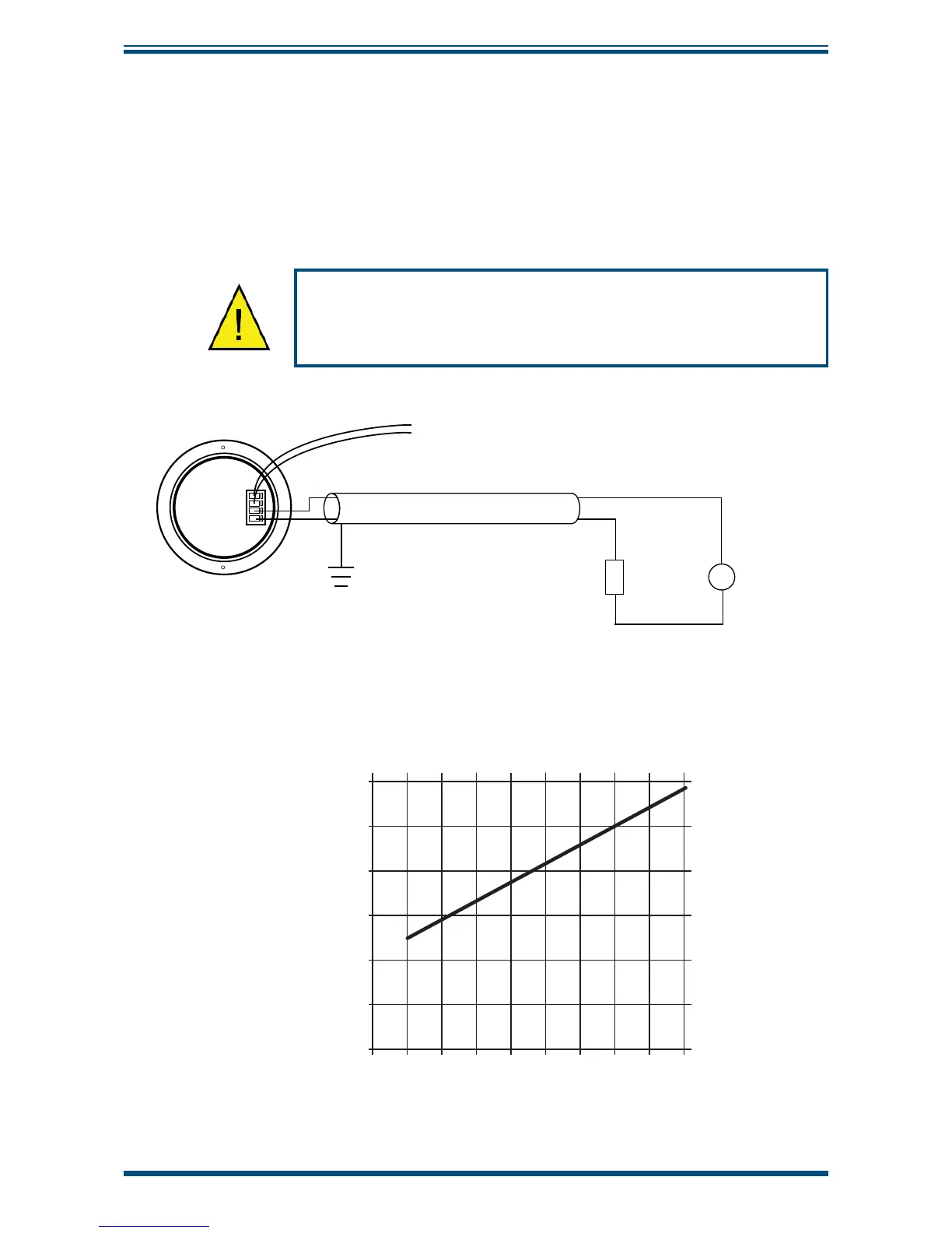
Always connect the 4-20 mA return signal to a suitable load
(see
Figure 16)
before the power is applied. Without this
connection, the transmitter may be damaged if allowed to
operate for prolonged periods.
+
-
LOAD
SUPPLY
Screen or Conduit
TRANSMITTER
LOOP POWER
+VE
VE
-
+VE
VE
-
g
g
From main transmitter pcb
Back of display module
Figure 12
Electrical Schematic
- Easidew PRO XP EX2 (Display)
2.7.3 Electrical Boundaries
100
200
300
400
500
600
12 14 16 18 20 22 24 26 28
Resistance (ohms)
Supply Voltage
Figure 13
Maximum Load of Easidew PRO XP - Including Cable Resistance