Microair Avionics M760 Transceiver Installation & User Manual
M760Q Install & User Manual 01R12.doc Page 5 of 36 30
th
March 2010
3.0 INSTALLATION
The M760 has a simple physical installation for aircraft instrument panels. Select or cut a 57mm (2 ¼”)
instrument hole for mounting (refer panel drilling template in section 9.0).
For panel locations which do not afford sufficient space behind the radio to reach the connectors, Microair
recommends connecting the wiring harness and coax cable before fitting the radio to the hole in the panel.
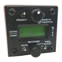
Present the M760 to the rear face of this hole. The stepped round face
will insert through the hole, and should appear flush with the front of
the instrument panel when correctly positioned. Rotate the M760 to
align the four M4 machine screws.
Loose fit all four M4 screws. For installations where the existing
instrument panel screw holes are 1/8”, the holes will need to be
enlarged to 5/32” to fit the M4 machine screws.
Insert and tighten all four M4 machine screws. The M760 requires no
rear support, the M4 screws provide all of the physical mounting
required.
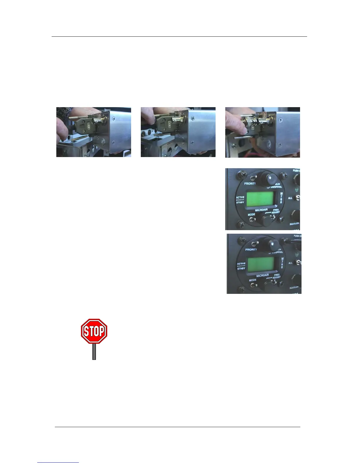
The M760 should be located in the aircraft within view of the pilot
seated in the pilot-in-command position, and afford this pilot good
access to the front face controls.
Do NOT oversize the mounting holes in the front face of the radio,
to an imperial size. Drilling will damage internal components.
Do NOT replace the M4 machine screws supplied with the radio
with longer screws. Over-length screws will touch or even crush
internal components and cause damage.
Either of these actions will void the warranty