Microair Avionics M760 Transceiver Installation & User Manual
M760Q Install & User Manual 01R12.doc Page 6 of 36 30
th
March 2010
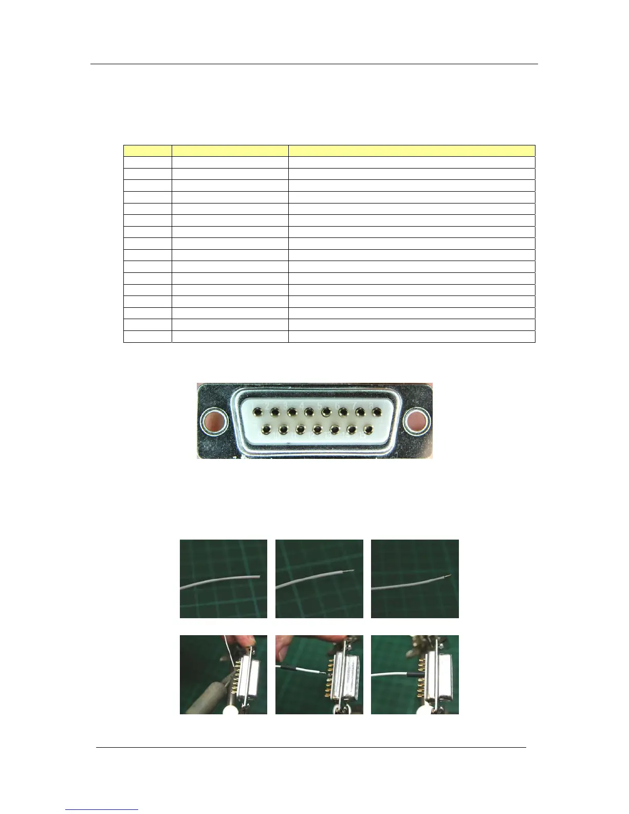
Bare Wire Soldered Wire Stripped Wire
Tinned Solder Cup Solder Wire to Cup Heatshrink
3.1 WIRING
Microair recommends the use of the wiring in the table below for the various parts of the radio harness:
Pin Line Wire
1 Pilot Microphone Tefzel 22 awg single core shielded
2 RS232 RX Tefzel 22 awg two core shielded (with RS232 TX)
3 Co-pilot Microphone Tefzel 22 awg single core shielded
4 Dual Comm Suppression Tefzel 22 awg
5 RS232 TX Tefzel 22 awg two core shielded (with RS232 RX)
6 Auxiliary Audio Input Tefzel 22 awg single core shielded
7 PTT Tefzel 22 awg two core shielded (with Memory)
8 Backlighting Tefzel 22 awg
9 Power Tefzel 22 awg
10 Power Tefzel 22 awg
11 Ground Tefzel 22 awg
12 Ground Tefzel 22 awg
13 Memory Tefzel 22 awg two core shielded (with PTT)
14 Headphone Tefzel 22 awg single core shielded (Pilot & Co-pilot)
15 Speaker Tefzel 22 awg single core shielded
BNC Aerial RG58C/U 50 ohm Coaxial Cable
All wiring is connected by soldering to the DB15 connector. Inspect the solder cup side of the DB15
carefully to determine the pin numbering.
Strip the insulation back 2mm (1/16”), and “tin” the exposed conductor with solder. Slide a 5mm length
of 1.6mm (1/16”) heatshrink tubing over the end of the wire. After checking the wiring diagram for the
correct pin number, push the “tinned” end into the “tinned” solder cup, and solder into place. Check the
soldered joint has been made, by gently pulling on the wire. Slide the heatshrink tubing down over the
soldered pin, to completely cover the conductor.