IP920 Operating Manual: Chapter 2 Electrical/Physical 5
COM1 –– RS-232 Port (DCE). This port is used to interface the IP920 to a
DTE device and operates at 300 to 230,400 bps. The levels are active high RS-
232 levels, and include (See Appendix A for a complete description):
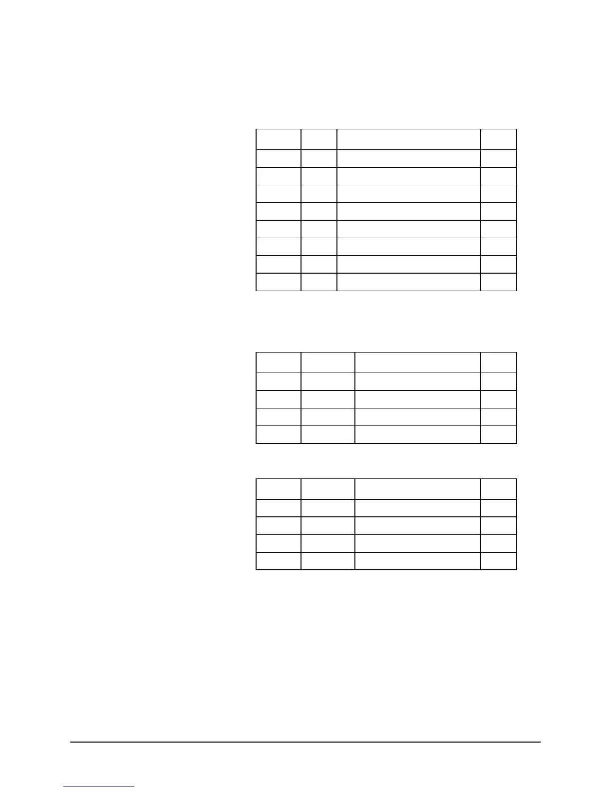
Table 1 RS-232 Pin Assignment
Pin No. Name Description I/O
1 DCD Data Carrier Detect O
2 RxD Receive Data O
3 TxD Transmit Data I
4 DTR Data Terminal Ready I
5 Gnd Ground
6 DSR Data Set Ready O
7 RTS Request to Send I
8 CTS Clear to Send O
RS-422/485 Port–Alternatively, this port is used to interface the IP920 to a
DTE device with RS-422/485 interface.
Table 2 RS-422 Pin Assignment
Pin No. Name Description I/O
1 TxB (D+) Non-inverting Driver Output O
2 TxA (D-) Inverting Driver Output O
3 RxB (R+) Non-inverting Driver Input I
4 RxA (R-) Inverting Driver Input I
Table 3 RS-485 Pin Assignment
Pin No. Name Description I/O
1 D+ Non-inverting Driver Output
2 D- Inverting Driver Output
3 Interconnect to pin 1
4 Interconnect to pin 2