46 IP920 Operating Manual: Chapter 5 Installation
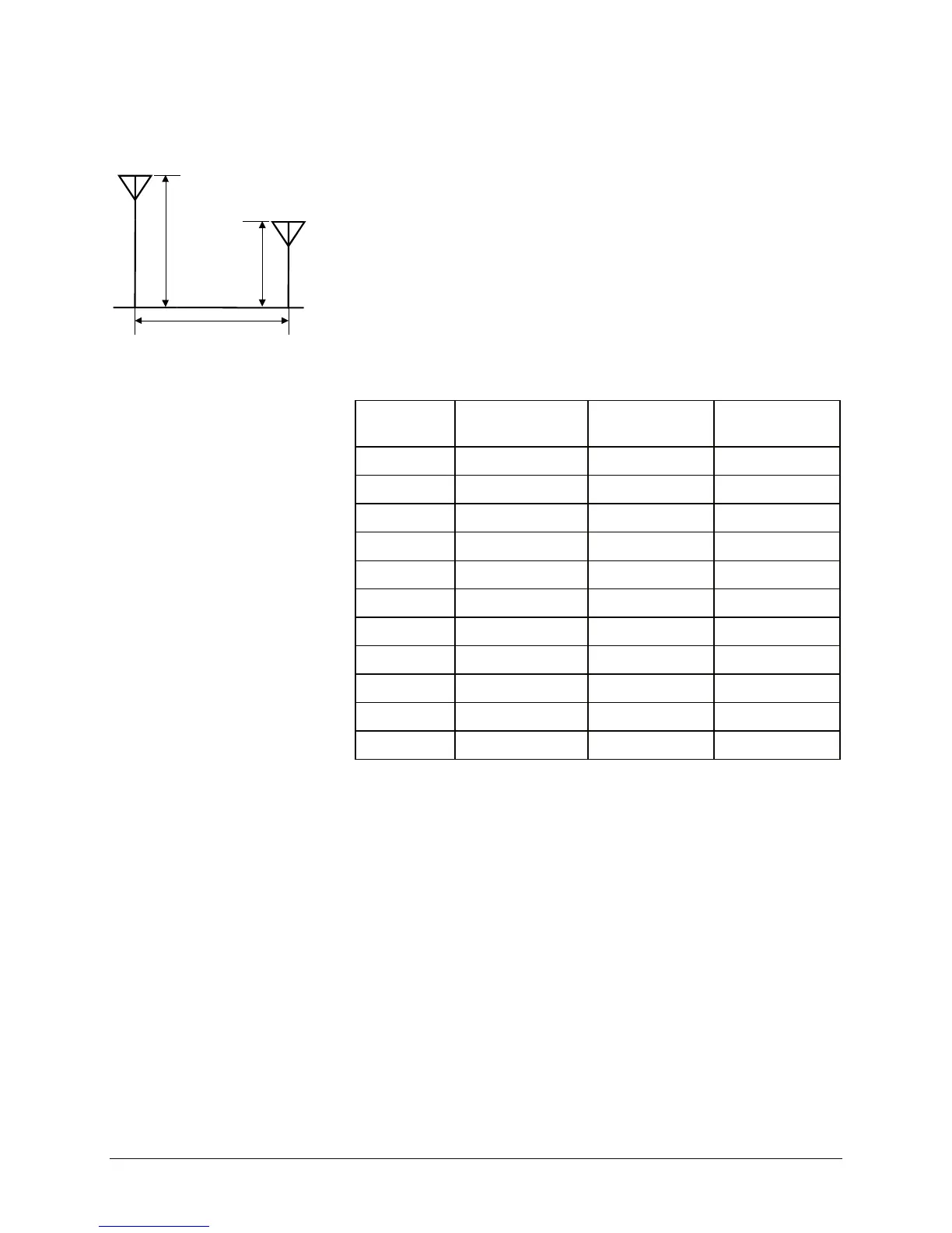
Base Height (m)
Mobile
Height
(m)
Distance (km)
Figure 24 System Deployment
When deploying your system, care must be taken to ensure the path loss
(reduction of signal strength from transmitter to receiver in dB) between
equipment does not exceed the system gain (143 dB in the above example).
It is recommended to design for a gain margin of at least 20 dB to ensure
reliable communication. Gain margin is the difference between system gain
and path loss. Referring to the same example, suppose the path loss is 113
dB, the gain margin would be 30 dB, which is more than adequate for
reliable communication.
Path loss is a very complicated calculation which mainly depends on the
terrain profile, and the height of the antennas off the ground.
The following table provides path loss numbers for varying antenna heights
and antenna separation: These numbers are real averages taken from rural
environments. They do not apply to urban, non-line-of-sight environments.
Table 10 Path Loss
Distance
(km)
Base Height
(m)
Mobile Height
(m)
Path Loss
(dB)
5 15 2.5 116.5
5 30 2.5 110.9
8 15 2.5 124.1
8 15 5 117.7
8 15 10 105
16 15 2.5 135.3
16 15 5 128.9
16 15 10 116.2
16 30 10 109.6
16 30 5 122.4
16 30 2.5 128.8
Once the equipment is deployed, you can verify the signal strength by
entering into Command Mode and reading Register S123. This register
provides the average signal strength in dBm. The minimum strength for
communication is roughly -106dBm. For consistent reliable
communication, you should try to deploy the equipment such that signal
strength exceeds -88dBm.