IP920 Operating Manual: Appendix B RS485 Wiring 53
B. RS485 Wiring
IP920 can be connected into 2-wire or 4-wire RS-485 network. Transmission line termination should be placed only
at the extreme ends of the data line if the RS-485 network runs at high data rates with long wiring.
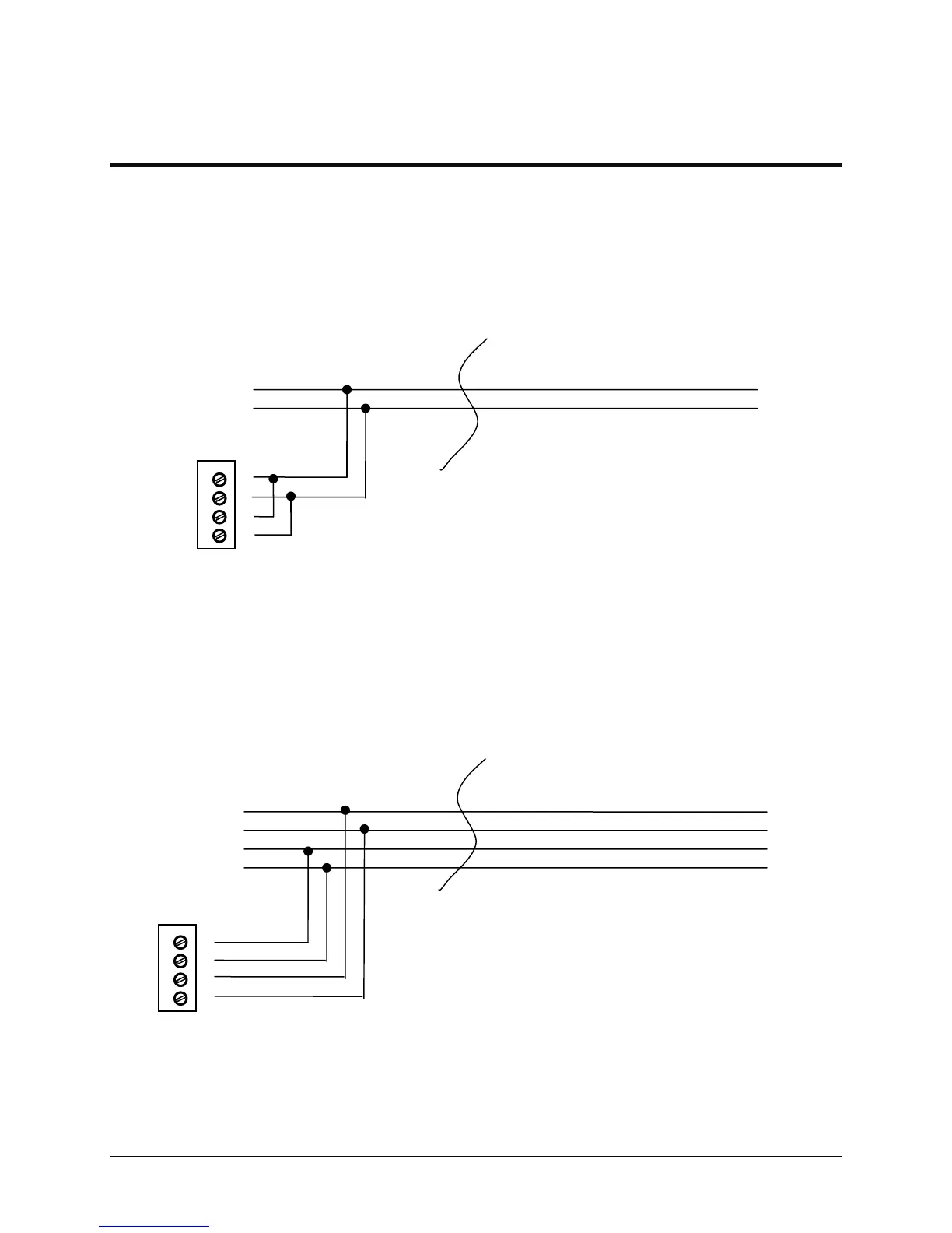
2-wire RS-485
Figure 25 shows a typical two-wire configuration of RS-485 IP920. Two wires are shared by transmission and
receiving in 2-wire configuration, so it is very important for the modem to grab the line at right time when it
transmits. Note again that the transmission line termination is needed if the system has high data rates and long
wiring runs.
4-wire RS-485
A IP920 RS-485 can also be connected into a RS-485 network in a four-wire fashion as shown in Figure 26. In a
four-wire network it is necessary that one node be a master node and all others be remotes. The network is
connected so that the master node communicates to all remote nodes. All remote nodes communicate only with the
master node. Since the remote nodes never listen to another remote response to the master, a remote node cannot
reply incorrectly to another remote node.
4
3
2
1
RxA (R-)
RxB (R+)
TxA (D-)
TxB (D+)
4
3
2
1
A (D-)
B (D+)
Figure 25 2-wireRS485 IP920
Figure 26 4-wire RS485 IP920