6 IP920 Operating Manual: Chapter 2 Electrical/Physical
COM2 – can be used as console port or data port. Table 4
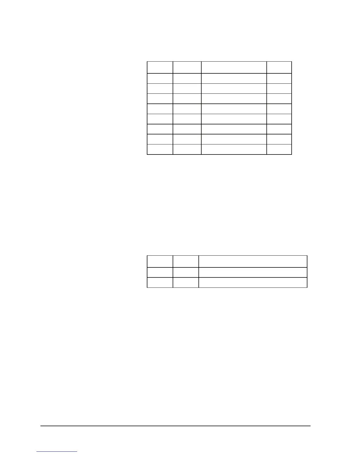
Table 4 Diagnostic Port Pin Assignment
Pin No. Name Description I/O
1 NC Do Not Connect NC
2 RxD Diagnostic Receive Data I
3 TxD Diagnostic Transmit Data O
4 NC Do Not Connect NC
5 Gnd Ground
6 NC Do Not Connect NC
7 NC Do Not Connect NC
8 NC Do Not Connect NC
ETHERNET –
Ethernet port is a standard RJ-45 port. A straight through CAT-
5 cable should be used when connecting to a Ethernet hub, on the other
hand, a crossover CAT-5 cable should be used when IP920 is connected
to a DTE device, a computer for example.
Antenna Connector - The IP920 uses a reverse polarity TNC connector.
Microhard Systems can provide external cabling and antennas for
applications in which the standard Rubber Duck antenna is not
suitable.
Power Supply–Power should be supplied via pin 5 and 6 of plug-in connector
Table 5 Power Supply
Pin No. Name Description
5 Vin - Power ground and Signal ground (GND)
6 Vin + 8 to 30V DC power supply