2: Installation
U3000/U4000 User Manual 13
(Issue 2.0)
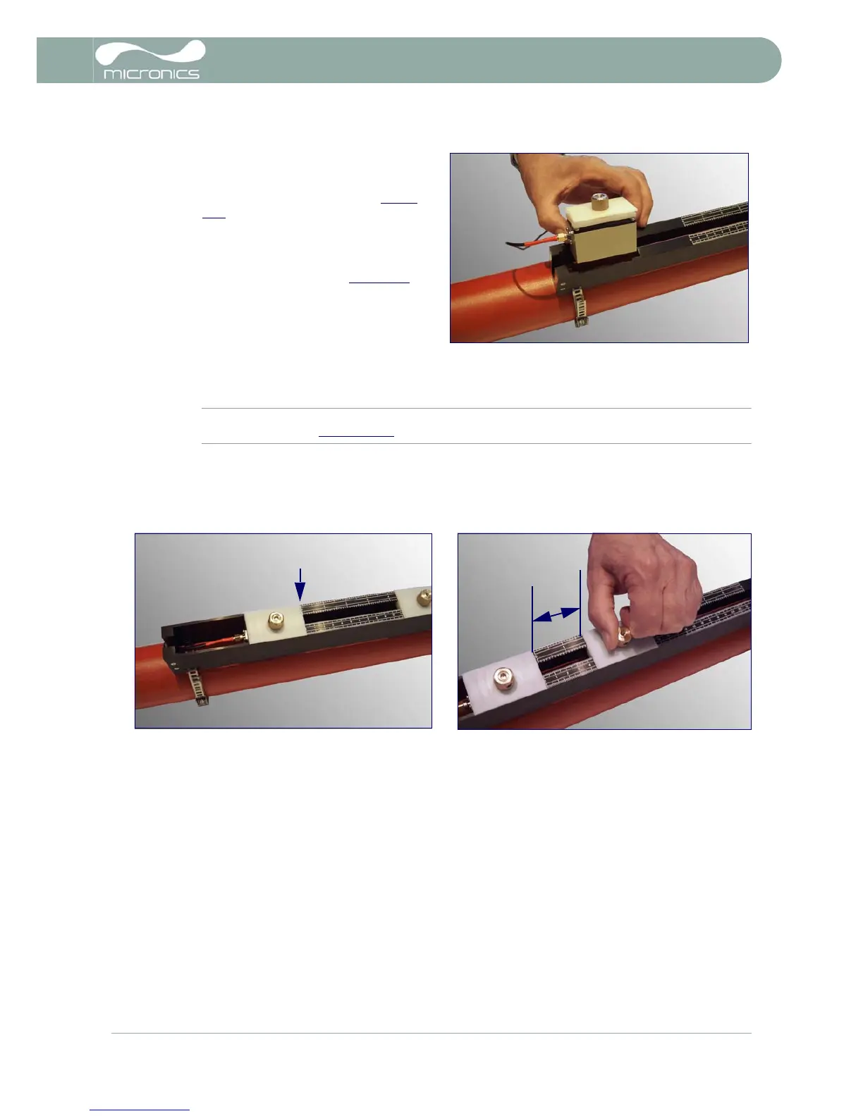
7. Connect the upstream signal cable (red) to
the other transducer and lower the
transducer assembly through the
rectangular opening, as shown in Figure
2.10.
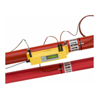
8. Position the upstream transducer at ‘0 on
the ruler scale and lower the transducer
onto the pipe by turning the thumb screw
anti-clockwise, as shown in Figure 2.11.
9. (See Note below.) Align the face of the right-
hand, downstream, transducer at the
calculated separation distance mark on the
ruler scale, then lower the transducer onto
the pipe by turning the thumb screw anti-
clockwise until firm contact with the pipe is
made.
Note: The correct separation distance for the particular application can be found using the ‘Quickstart’
menu as described in Paragraph 3.2.
10. Finally lock the thumb screws in position by fitting the two M5 locknuts supplied.
11. Ensure the transducer signal cables are correctly connected to the U3000/U4000 instrument – i.e. with
the RED cable is connected to the upstream transducer connector and the BLUE cable to the
downstream transducer connector.
Figure 2.10
Figure 2.11