3: Operating Procedures
20 U3000/U4000 User Manual
(Issue 2.0)
15. The SENSOR SEPARATION screen now
displays a summary of the entered
parameters and informs you of the type of
sensor to be used, the mode of operation
and the distance to set up between the
sensors.
In this example it recommends type A-ST
(A standard) sensors operating in the
‘Reflex’ mode spaced at 44.64mm apart.
Take a note of these details
Note: Do not press ENTER until the transducers are fitted and connected to the instrument.
Password Control
After data has been entered for the first time, the U3000/U4000 password control feature is ‘enabled’ when
you exit from Quick start to the FLOW READING screen. This prevents unauthorised tampering of the set-
up data. Once ‘enabled’, a password control box is displayed if any key is pressed and you must then enter a
5-digit password code to ‘disable’ the password control and gain access to any of the menus.
Note: Once disabled, the password control feature is re-enabled if no keys are pressed for five minutes.
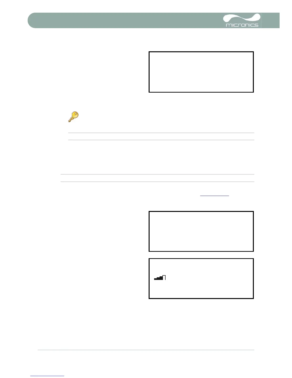
Attaching and connecting the transducers
16. Fit the designated sensors to the pipe using the guide rail as described in Paragraph 2.3.3
. The
separation distance must be set to within ±0.5mm.
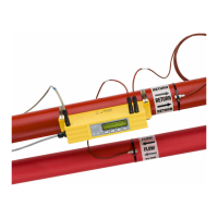
Taking a flow reading
17. Once the transducers have been fitted and
connected press the ENTER key.
18. This will take you from the SENSOR
SEPARATION screen to the FLOW
READING screen via the signal-checking
screen (shown here).
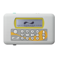
19. Check that the indicated signal strength on
the left of the screen shows at least 2 bars
(ideally 3 or 4). If less than 2 bars are
shown it indicates there could be a problem
with the transducer spacing, alignment or
connections; or an application problem.
Flow monitoring
The FLOW READING screen is the one most used during normal monitoring operation. It shows the
instantaneous fluid flow together with totalised values (when enabled). In this mode you can select the flow
rate measurement units by pressing keys 7 (litres), 8 (Gallons, Barrels) or 9 (m³), or change the display to
show velocity by pressing key 4.
Key Point: The above example shows the spacing required using a ‘type A’ probe
set, as supplied with the model U3000/U4000A.