20 M AIR User Manual
3. Engage the 48 V phantom power by pressing and holding this button.
It is best practice to engage phantom power before running audio in
a channel, allowing all voltages to stabilize and prevent any noise
during the performance.
4. Adjust the analog input Gain with this control.
5. Engage an eect Insert and select the FX bus that will be inserted.
6. The source for the channel’s physical input and USB input can be selected
with these pull-down menus.
7. Select whether the analog input or USB input appears at this channel.
8. The S/E button appears at the top of many edit pages, and oers the option
to view a simple or expanded set of controls, especially for the Gate and
Dynamics pages.
9. Engage the Low Cut with this button to remove unwanted low frequencies.
10. Adjust the digital Trim for the USB input with this control.
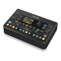
6.4 Gate
The Gate tab allows a noise gate to be engaged and adjusted to remove
unwanted noise. Using the S/E button, a simple or expanded set of parameters
can be selected to accommodate various levels of mixing expertise. Presets can
also be selected from the folder icon to automatically load settings that suit
yourapplication.
1. Engage the gate with the ON button.
2. The function menu allows various types of gates to be selected. The EXP
2, 3 and 4 settings expand the dynamics by attenuating signals below
the threshold by factors of 2:1, 3:1 and 4:1 respectively. The Gate setting
completely cuts o signals below the threshold. The Ducker setting
attenuates the signal by a predetermined amount whenever the signal
rises beyond the selectedthreshold. This eect is usually controlled by an
external key source, such as another channel's signal. Change the key source
from “self” to any other channel (see callout #9).
3. Adjust the Threshold that the audio must reach in order to bypass the gate or
engage the Ducker.
4. The Range parameter adjusts the amount of attenuation for the
GateandDucker.
5. Adjust the Attack knob to set how quickly the gate takes eect when the
input signal drops below the threshold.
6. Adjust the Hold knob to set how long the input signal must surpass the
threshold before bypassing the gate.
7. Adjust the Release knob to set how quickly the gate releases after the audio
rises above the threshold.
8. Engage the key lter with the Key On button.
9. Select a low cut, high cut or mid peak frequency and bandwidth/slope for
ltering the key signal that is controlling the gate. The key source is usually
set to “self”. Choosing a dierent key source allows another channel or bus
to control the gate, e.g. for ducking the hi-hat channel whenever the snare
drum is hit.
10. Select the frequency for the key lter.
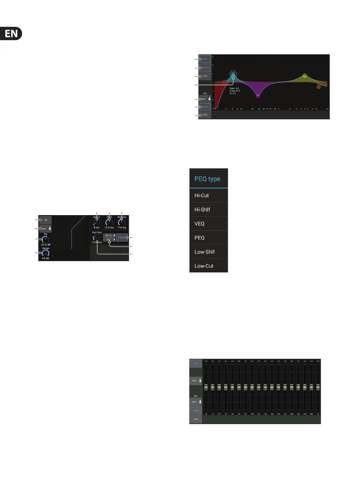
6.5 EQ
1. Engage the EQ with the ON button.
2. Engage the Lowcut button to remove unwanted low frequencies.
3. Select the type of EQ for the selected band. This menu will only be available
when one of the 4 bands are active, not including the lowcut.
4. Drag the band button left and right to determine the specic frequency,
andmove it up and down to determine the amount of boost or cut.
Useapinch or spread gesture (zoom in/out) to alter the bandwidth/Q.
5. Select the source for the RTA to display.
6. To automatically send the channel that you are currently editing to the RTA,
press the Follow button.
7. Press the Post button to display the post-EQ results in the RTA.
Graphic EQ
(1)
(2)
(3)
(4)
(5)
(6)
(7)
(8)
(9)
(10)
(1)
(2)
(3)
(5)
(6)
(7)
(4)