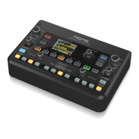
26 M AIR User Manual
10. Select the type of lter and frequencies with these faders.
11. Select a channel or bus for the side chain from the pull-down menu. For the
gate and expander functions, the key lter is usually set to “self”, but the
ducker can use another channel's signal to trigger the desired attenuation.
7. 5 EQ Tab
1. Engage the Low Cut and adjust the specic frequency to remove
unwanted lows.
2. Turn the equalizer on and o with the EQ button. If a bus output is selected,
a graphic EQ can also be engaged with the options below the EQ button.
3. Use the Reset button to return all bands to their default settings.
A conrmation box will pop up to prevent accidental resets.
4. Select the Mode from the pull-down menu. PEQ types will often be used for
the rst 3 bands, and a high cut or high shelf for the 4th band.
5. The currently-active band will be indicated on this button.
6. Click this button to turn a specic band on and o. This is useful for A/B
testing how an adjustment aects the signal.
7. The gain adjustment for each band can be manually entered here, or you can
click and drag the band's corresponding number up and down.
8. The bandwidth (Q) can be manually entered here. Alternatively, you can
place the mouse over the numbered dot for an EQ band and change the
bandwidth with the mouse wheel.
9. Each band’s specic frequency can be manually entered, or you can click and
drag the band's number to the desired frequency.
10. Engage the Spectrograph function to change from the standard RTA view to
a spectrogram, which displays the signal energy over time. This can be useful
for identifying feedback or phasing problems.
11. Press the Pre button to display the RTA pre-EQ rather than post-EQ.
12. Engage the RTA (Real Time Analyzer) with this button.
7.6 Comp Tab
1. Select one of the 4 Presets to automatically optimize the parameters for one
of these common sources.
2. Engage the Compressor with this button.
3. Adjust the Threshold at which the compressor begins to take eect.
Audio that falls below this setting will remain unaected.
4. Select between a Compressor or Expander to set the action of the dynamics
processor. While a compressor reduces a signal's dynamics, an expander
increases the dynamic range.
5. Select a Knee angle to set how gradual the compressor takes eect.
When set to 0, any signals that rise above the threshold will receive the full
compression ratio.
6. Select between Peak and RMS input response. RMS is most common
in compressors and responds to the average level of incoming audio,
whereas the Peak setting responds to brief spikes in loudness that would be
allowed through when set to RMS.
7. Select between an aggressive Linear or smooth Logarithmic operation.
8. Adjust the Ratio to determine how aggressively the dynamics are aected.
9. Adjust the Mix to determine how much of the signal is left unaected by
the processor, commonly called parallel or "New York" compression.
10. Adjust the Gain to compensate for changes in level caused by the processor.
11. Engage the Auto Time to allow several of the more advanced parameters to
be automatically adjusted according to the input signal.
12. Adjust the Attack to set how quickly the compressor takes eect when the
input signal rises above the threshold.
13. Adjust the Hold to set how long the compressor takes to enter the release
cycle once the audio drops below the threshold.
14. Adjust the Release to set how quickly the compressor releases after the audio
drops below the threshold.
15. Engage the key Filter with this button.
16. Select the type of lter and frequencies with these faders.
17. Select a channel or bus for the side chain input from the pull-down
menu. In most applications, a channel's own signal will be used to trigger
the compressor, and therefore the key lter should be set to “self”.
However, a technique called “sidechain” compression can be achieved by
selecting another channel as the key source.
7.7 Sends Tab
The Sends tab allows the currently-selected channel's signal to be routed to the
6 Aux buses and to the 4 FX processors. These adjustments can also be made on
the Channel tab, or by selecting one of the Fader Bank layers on the lower right-
hand side of the main view screen. The signal can be routed to the buses from
specic points in the preamp chain, such as pre or post EQ and pre or post fader.
Clicking the globe icon will enable changes to the tap point (pre/post fader, etc)
to take eect on all channels.
(1)
(10) (11)
(4)
(2) (3) (5) (6) (12)
(7) (8) (9)
(8) (9) (10) (12) (13) (14)
(1)
(2) (5) (11) (15) (17)(6)(7)(3) (4)
(16)