25 M AIR User Manual
1. Click the FX button to engage an insert eect. The specic FX block is
selected with the adjacent pull-down menu.
2. The Stereo Link button allows a channel to be paired with the adjacent
channel in a stereo pair. The fader level, gain setting, bus sends, etc. will
be the same between the 2 channels, and the pan will default to hard
left and right. The odd-numbered channel will always be the lower of
the pair. See chapter 7.11 for available link preferences on the Setup -
Audio/MIDI page.
3. The Phantom button engages the 48 V phantom power for use with
condenser microphones and active DI boxes.
4. The Polarity button inverts the phase.
5. Click the USB button to route the USB return signal to the selected channel
instead of the analog input.
6. The analog Mic Gain and digital USB Trim can be adjusted independently,
though only one source can be used at a time.
7. The Noise Gate can be engaged and the threshold can be adjusted from this
page. More detailed controls are available on the Gate tab.
8. The Equalizer and Low Cut can be engaged here, as well as the
low cut frequency.
9. The Compressor can be engaged and its threshold adjusted here.
More detailed controls are available on the Comp tab.
10. The channel Aux Bus Sends can be adjusted here as well as the Sends tab.
11. The Main Out section allows the channel to be routed to or removed from the
main bus. The pan can also be adjusted, and the Auto Mix, DCA Group and
Mute Group assignments can be selected here as well.
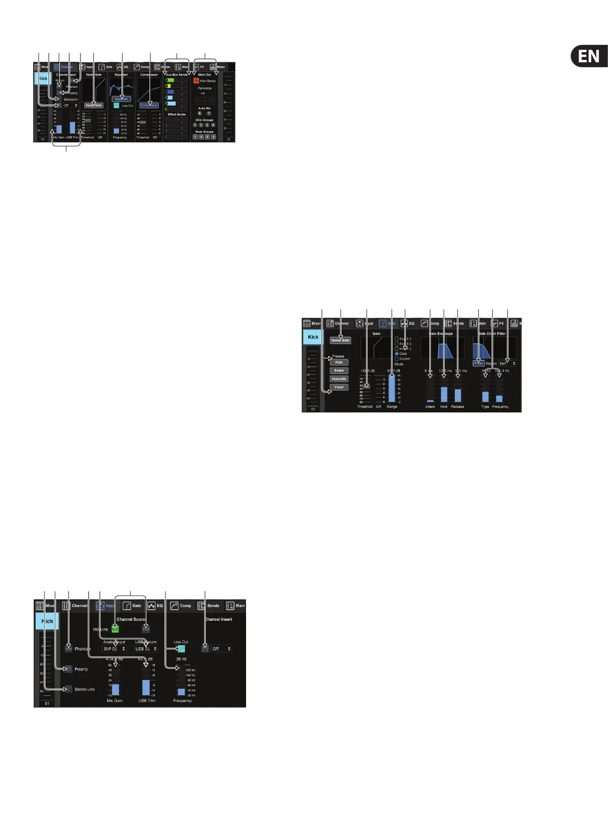
7. 3 Input Tab
The Input tab allows adjustment of the most common preamp parameters as well
as specic routing for the input and insert.
1. The Stereo Link button allows a channel to be paired with the adjacent
channel in a stereo pair. The fader level, gain setting, bus sends, etc. will be
the same between the 2 channels, and the pan will default to hard left and
right. The odd-numbered channel will always be the lower of the pair.
2. The Polarity button inverts the phase.
3. The Phantom button engages the 48 V phantom power for use with
condenser microphones and active DI boxes. It is recommended to engage
phantom power well ahead of running audio in a channel in order to allow
all voltages to stabilize and prevent any noise during performance.
4. The analog Mic Gain and digital USB Trim can be adjusted independently,
though only one source can be used at a time.
5. The analog input and USB input channels default to a 1:1 relationship to the
channel number, but can be re-routed using the pull-down menus.
6. Select whether the analog mic/line input or the USB input appears in
the channel.
7. Engage the Low Cut and adjust the specic frequency to remove
unwanted lows.
8. Click the FX button to engage an insert eect. The specic FX block is
selected with the adjacent pull-down menu.
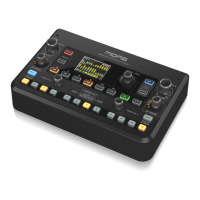
7.4 Gate Tab
The Gate tab allows a noise gate to be engaged and adjusted to automatically
remove unwanted noise.
1. Select one of the 4 Presets to automatically optimize the parameters for one
of these common sources.
2. Engage the Noise Gate with this button.
3. Adjust the Threshold that the audio must reach in order to bypass the gate or
engage the ducker.
4. The Range parameter adjusts the amount of signal attenuation for the Gate
and Ducker settings.
5. Select the type of eect from the 5 options. Expander eects are available
with 2:1, 3:1 and 4:1 ratios which reduce the output by varying amounts,
allowing a natural sounding reduction of signals that don’t reach the
selected threshold. The Gate setting enables a more aggressive drop in
volume for signals below the threshold. An additional Range parameter
adjusts the amount of attenuation. The Ducker setting attenuates the signal
by an adjustable amount whenever the signal rises beyond the selected
threshold. The Range parameter adjusts the amount of attenuation for this
setting as well.
6. Adjust the Attack parameter to set how quickly the gate opens up when the
signal rises above the threshold.
7. Adjust the Hold parameter to set how long the gate will stay open after the
signal drops below the threshold.
8. Adjust the Release parameter to set how quickly the gate will close after the
hold time has ended.
9. Engage the key Filter with this button, which can be used to emphasize
the specic frequency range that will open up the gate, or exclude certain
frequencies that you do not want to aect the gate.
(3) (7) (9)(8)
(1)
(10)
(2) (4) (5)
(6)
(11)
(2) (3) (8)(7)(1) (5) (6)(4)
(1)
(2) (3) (4)
(6)
(7) (8) (9) (11)(5) (10)