This document is a service manual for Midea V6 VRF (Variable Refrigerant Flow) commercial air conditioners, operating on R410A refrigerant at 50/60Hz. It provides comprehensive information for technicians on the system's components, control logic, field settings, electrical diagrams, and troubleshooting procedures.
Function Description
The Midea V6 VRF system is designed for commercial air conditioning applications, offering both cooling and heating functionalities. It utilizes a multi-unit setup, where outdoor units are combined to meet the total capacity requirements of various indoor units. The system incorporates advanced control schemes to optimize performance, ensure reliability, and provide protection against abnormal operating conditions. Key functional components include compressors, heat exchangers, electronic expansion valves (EXVs), oil separators, accumulators, and various sensors and solenoid valves, all working in concert to manage refrigerant flow and system pressure.
Important Technical Specifications
The manual details a wide range of indoor and outdoor unit capacities and combinations.
Indoor Units:
Standard indoor units are available in various types:
- Cassette: One-way (Q1), Two-way (Q2), Compact Four-way (Q4C), Four-way (Q4)
- Duct: Medium Static Pressure (T2), High Static Pressure (T1)
- Other: Wall-mounted (G), Ceiling & Floor (DL), Floor Standing (F), Console (Z)
Capacities for standard indoor units range from 1.8 kW (0.6 HP) to 56.0 kW (20 HP).
Fresh air processing units are available with capacities from 12.5 kW to 56 kW, and small airflow rate units from 14 kW to 28 kW.
Heat recovery ventilators offer airflow rates from 200 m³/h to 2000 m³/h.
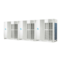
Outdoor Units:
Single outdoor unit capacities range from 8 HP (MV6-252WV2GN1) to 32 HP (MV6-900WV2GN1).
Combinations of outdoor units allow for larger system capacities, from 34 HP (12HP+22HP) up to 96 HP (32HP+32HP+32HP).
The combination ratio of indoor to outdoor unit capacity indexes has limitations: a minimum of 50% and a maximum of 130% for standard indoor units only, or 100% for fresh air processing units only, or 100% when both are used (with fresh air units not exceeding 30% of total outdoor unit capacity).
Components Layout and Refrigerant Circuits:
The manual provides detailed diagrams of functional components for 8/10/12HP, 14/16HP, 18/20/22HP, and 24/26/28/30/32HP outdoor units.
Key components include:
- Compressor (1): The heart of the refrigeration cycle.
- Temperature sensors: Discharge gas (2), Heat exchanger (T3), Outdoor ambient (T4), Plate heat exchanger inlet (T6A) and outlet (T6B), Compressor A/B discharge (T7C1/T7C2).
- Pressure switches/sensors: High pressure switch (3), High pressure sensor (4), Low pressure switch (9).
- Oil separator (5): Separates oil from refrigerant gas and returns it to the compressor.
- Four-way valve (6): Controls refrigerant flow direction for heating/cooling.
- Heat exchanger (7): Facilitates heat transfer.
- Electronic expansion valve (EXV) (8): Controls refrigerant flow and pressure. Multiple EXVs (EXVA, EXVB, EXVC) are used in larger systems.
- Fan motor (10) and Fan (11): Drive airflow through the outdoor heat exchanger.
- Stop valves: Liquid side (12), Gas side (13).
- Plate heat exchanger (14): Improves super-cooling in cooling mode and enhances heating capacity in low ambient temperatures.
- Accumulator (15): Stores liquid refrigerant and oil to protect the compressor.
- Solenoid valves: SV4 (oil return), SV5 (fast defrosting/unloading), SV6 (EXV bypass), SV7 (indoor units bypass), SV8A/SV8B (compressor vapor injection), SV9 (compressor B pressure balance).
Usage Features
The system incorporates various control features to ensure efficient and reliable operation:
- General Control Scheme: Includes stop operation, standby control (crankcase heater control), startup control, normal operation control, protection control, and special control.
- Startup Control: Compressors have a delay for initial startup (12 minutes) and restart (7 minutes) to equalize pressure and prevent frequent on/off cycles.
- Compressor Output Control: Compressor speed is adjusted based on indoor unit load requirements and ambient temperature.
- Compressor Step Control: Running speed can be altered in 1 rps increments.
- Operating Priority and Rotation: In multi-compressor units, inverter compressor A (BP1) has priority over inverter compressor B (BP2). In multi-outdoor unit systems, units operate in rotation.
- Electronic Expansion Valve Control: EXVs are controlled in steps from 0 (fully closed) to 480 (fully open), based on discharge temperature, superheat, or temperature differences across the plate heat exchanger.
- Outdoor Fan Control: Fan speed is adjusted in steps (rpm) to optimize performance.
- Special Control:
- Outdoor Unit Duty Cycling: Prevents compressor burnout due to unbalanced oil levels in multi-unit systems, activated after oil return, defrosting, or restart.
- Oil Return Operation: Recovers oil from the piping system to prevent compressor oil starvation, performed periodically (e.g., every 8 hours after initial 140 minutes of operation).
- Defrosting Operation: Recovers heating capacity when the outdoor heat exchanger acts as an evaporator, controlled by outdoor ambient temperature, heat exchanger temperature, indoor heat exchanger temperature, and running time.
- Field Settings: Outdoor unit main PCB switches (S4, S5, S6-1, S6-2, S6-3, S8-1, S8-2, S8-3, S7, S9) and ENC (ENC1, ENC2, ENC3, ENC4, ENC5) allow for customization of static pressure, priority mode, indoor unit addressing, outdoor unit capacity, network address, number of indoor units, and silent mode settings.
- Priority Modes: Auto priority (default, switches between heating/cooling based on ambient temperature), Heating priority, Cooling priority, VIP priority (unit with VIP address dictates mode), Voting priority (majority mode wins), Heating only, Cooling only.
- Silent Mode: Reduces fan speed and/or compressor frequency to lower noise levels, with various settings for night silent time and super silent modes.
Maintenance Features
The service manual provides extensive troubleshooting and diagnostic information:
- Error Code Table: Lists various error codes (E0, E1, E2, E4, E5, E7, E8, xE9, xF1, F3, F5, xF6, xH0, H2, H3, xH4, H5, H6, H7, H8, yHd, P1, P2, xP3, P4, P5, P9, H9, PL, C7, PP, xL0-xL9) with their content, remarks, and whether a manual restart is required.
- Troubleshooting Procedures: Detailed flowcharts guide technicians through diagnosing and resolving each error code, including possible causes and recommended actions (e.g., checking wiring, sensors, power supply, refrigerant levels, component replacement).
- Digital Display Output: Explains how to interpret DSP1 and DSP2 displays for unit status, parameters, and error codes.
- Menu Mode Function: Describes how to access and navigate the menu mode on the master unit PCB to check debug information, maintenance mode, history error codes, power limitation settings, temperature unit settings, auto snow-blowing modes, and VIP address settings.
- LED Indicators: Inverter module LED indicators (LED1, LED2) flash in specific patterns to indicate different error codes (xL0, xL1, xL2, xL4).
- Component Inspection: Guidance on inspecting compressor oil (color, impurities) and the effects of spoiled oil on compressor components (worn crankshaft, scroll plate, bearings, blocked filter).
- Temperature Sensor Resistance Characteristics: Tables provide resistance values for outdoor ambient, outdoor heat exchanger, compressor top, discharge pipe, and inverter module temperature sensors at various temperatures, aiding in sensor testing.
- Normal Operating Parameters: Tables provide expected ranges for discharge temperature, superheat, discharge pressure, suction pressure, and DC inverter compressor current in both cooling and heating modes under different ambient temperatures, useful for verifying system performance.
The manual emphasizes safety warnings, particularly regarding electrical work and power disconnection before servicing. It also highlights the importance of using correct oil types and quantities for compressors.