V6 VRF 50/60Hz
89
Part 6 - Diagnosis and Troubleshooting
Procedure
F1
Compressor inverter module
wiring loosened
Yes
Reconnect cables based on
wiring diagram
Disconnect the
power supply
No
Reactor and DC bus wiring is
incorrectly
1
Yes
Reconnect the reactor and
DC bus wire based on wiring
diagram
No
The power supply is abnormal
Check the power supply
equipment
Replace the inverter module
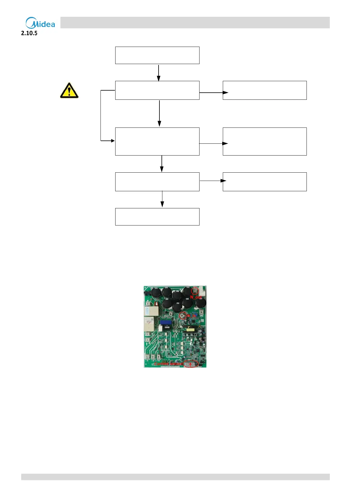
Note:
1. The DC bus wire should run from the N_in terminal on the inverter module, through the current sensor (in the direction indicated by the
arrow on the current sensor), and end at the N_out terminal on the inverter module.
Figure 6-2.2: DC detection wire connection method