V6 VRF 50/60Hz
101
Part 6 - Diagnosis and Troubleshooting
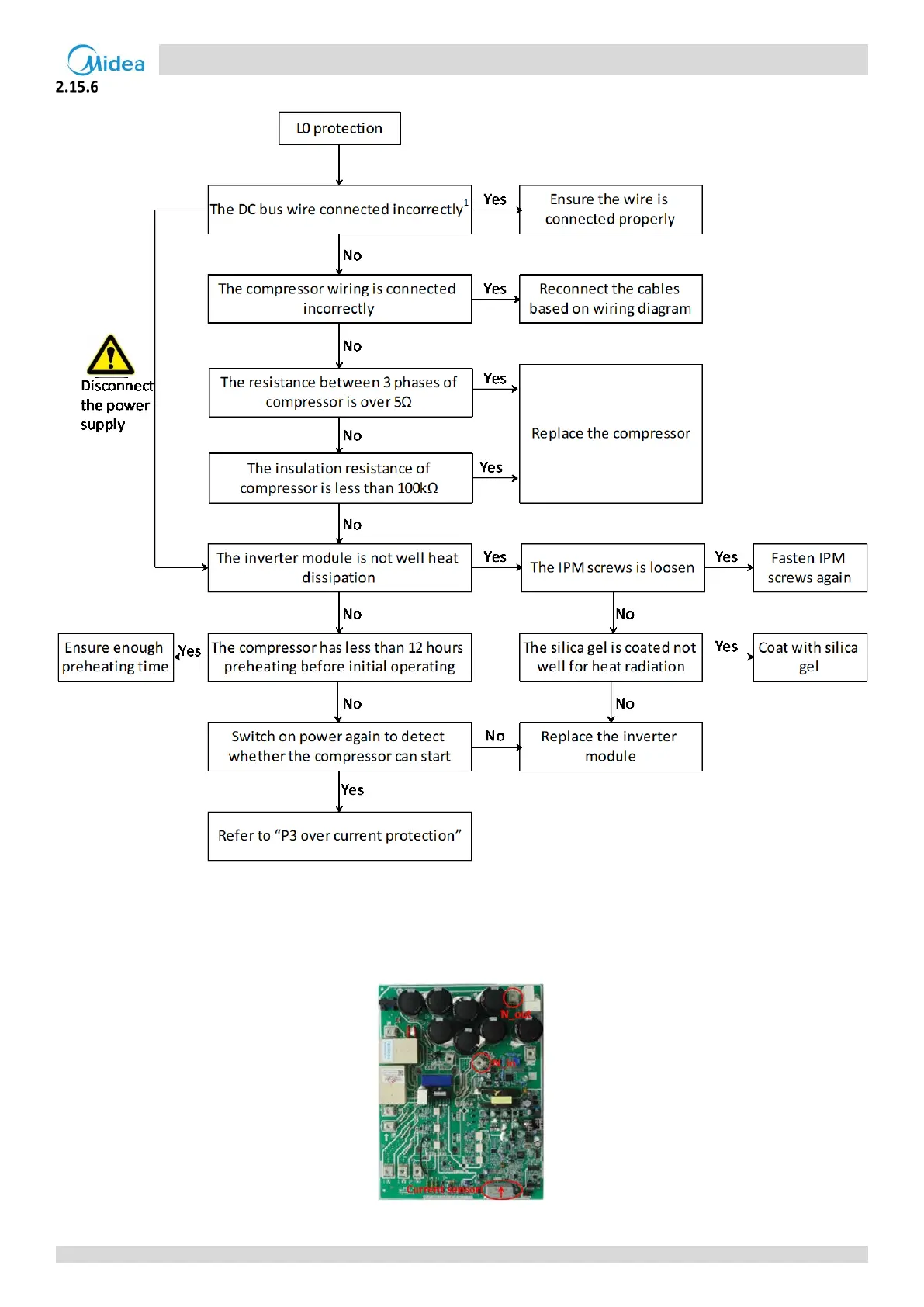
L0: Inverter module protection
Note:
2. The DC bus wire should run from the N_in terminal on the inverter module, through the current sensor (in the direction indicated by the
arrow on the current sensor), and end at the N_out terminal on the inverter module.
Figure 6-2.5: DC detection wire connection method