V6 VRF 50/60Hz
37
4.3 Startup Control for Heating Operation
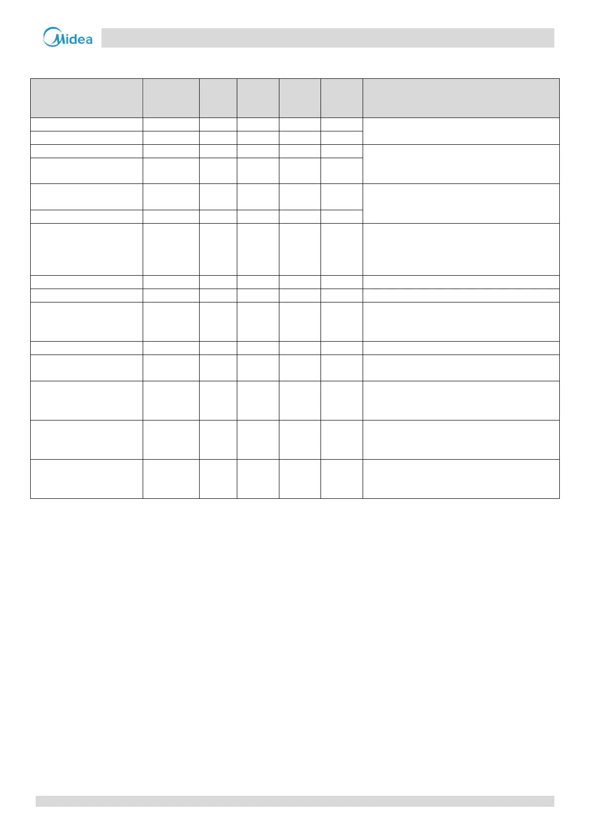
Table 3-4.2: Component control during startup in heating mode
Component
Wiring
diagram
8-12HP 14-16HP 18-28HP 30-32HP Control functions and states
● ● ● ●
Controlled according to load requirement,
operating frequency increased by 1 step / sec
● ●
● ● ● ● Open once the four-
way valve has opened,
controlled according to outdoor ambient
temperature and load requirement
DC fan motor B FANB ● ●
E
lectronic expansion valve
A
EXVA ● ● ● ●
Position (steps) from 0 (fully closed) to 480 (fully
open), controlled according to discharge superheat
Electronic expansion valve B
● ● ●
Electronic expansion valve C EXVC ● ● ● ●
Position (steps) from 0 (fully closed) to 480 (fully
open), controlled according to temperature
different between plate heat exchanger inlet and
outlet
● ● ● ●
Solenoid valve (oil balance)
● ● ● ●
Closed for 200 secs, open for 600 secs, then closed
defrosting (in heating) and
SV5 ● ● ● ● Open for 4 mins, then closed
Solenoid valve (EXV bypass)
● ● ● ●
Solenoid valve (indoor units
SV7 ●
● Controlled according to load requirement
Solenoid valve (inverter
c
ompressor A vapor
injection)
SV8A ● ● ● ● Controlled according to inverter compressor A
Solenoid valve (inverter
compressor B vapor
SV8B ● ● Controlled according to inverter compressor B
Solenoid valve (inverter
compressor B pressure
SV9 ● ● Open before compressor B startup