V6 VRF 50/60Hz
65
Part 5 - Electrical Components and Wiring Diagrams
3 Compressor Inverter Module
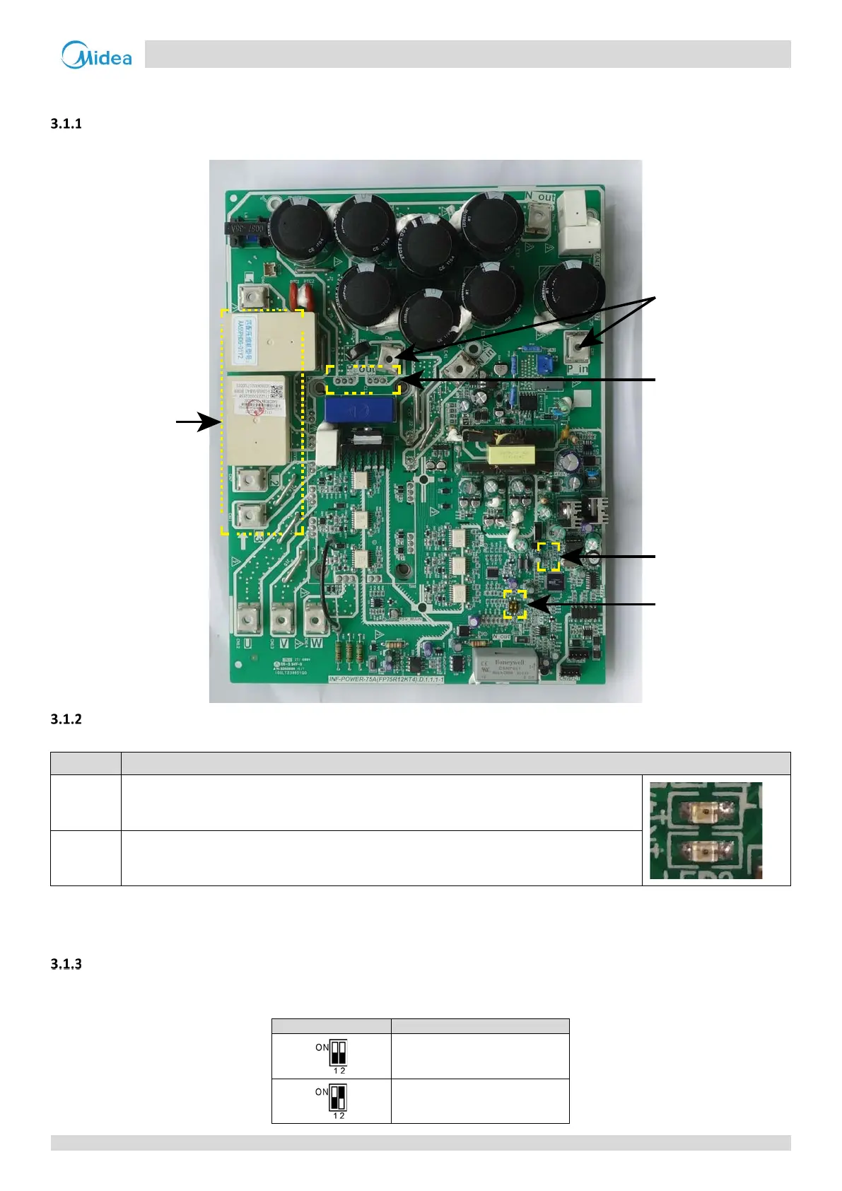
Layout
Figure 5-3.1: Compressor inverter module components
LED indicators LED1 and LED2
Table 5-3.1: LED indicators LED1 and LED2
Indicator LED indicator function and status
LED 1
Inverter module operating indicator. Continuously on(green color) if the compressor is running
normally and flashing(green color) if an inverter module error has occurred
1
.
LED 2
Inverter module error indicator. Continuously on(red color)if an
inverter module error has
occurred
1
.
Note:
1. If an inverter module error occurs, refer to Part 6, “Xh4 Troubleshooting”. The error code is displayed on the digital display.
Dial switch S7 setting
Dial switch S7 is used to set compressor inverter module A/B address. The compressor inverter module A/B location refers
to the wiring diagram.
0 for compressor inverter module A
1 for compressor inverter module B
3-phase bridge
rectifier power
input
3-phase bridge
rectifier power
output
LED1 / LED2
Dial switch S7
Connect to
reactor