V6 VRF 50/60Hz
48
Midea V6 Series Service Manual
7.3 Defrosting Operation
In order to recover heating capacity, the defrosting operation is conducted when the outdoor unit heat exchanger is
performing as an evaporator. The defrosting operation is controlled according to outdoor ambient temperature, outdoor
heat exchanger temperature, indoor heat exchanger temperature and outdoor units running time. When the outdoor unit
is running in defrosting, the digital display on outdoor main PCB will display “df”.
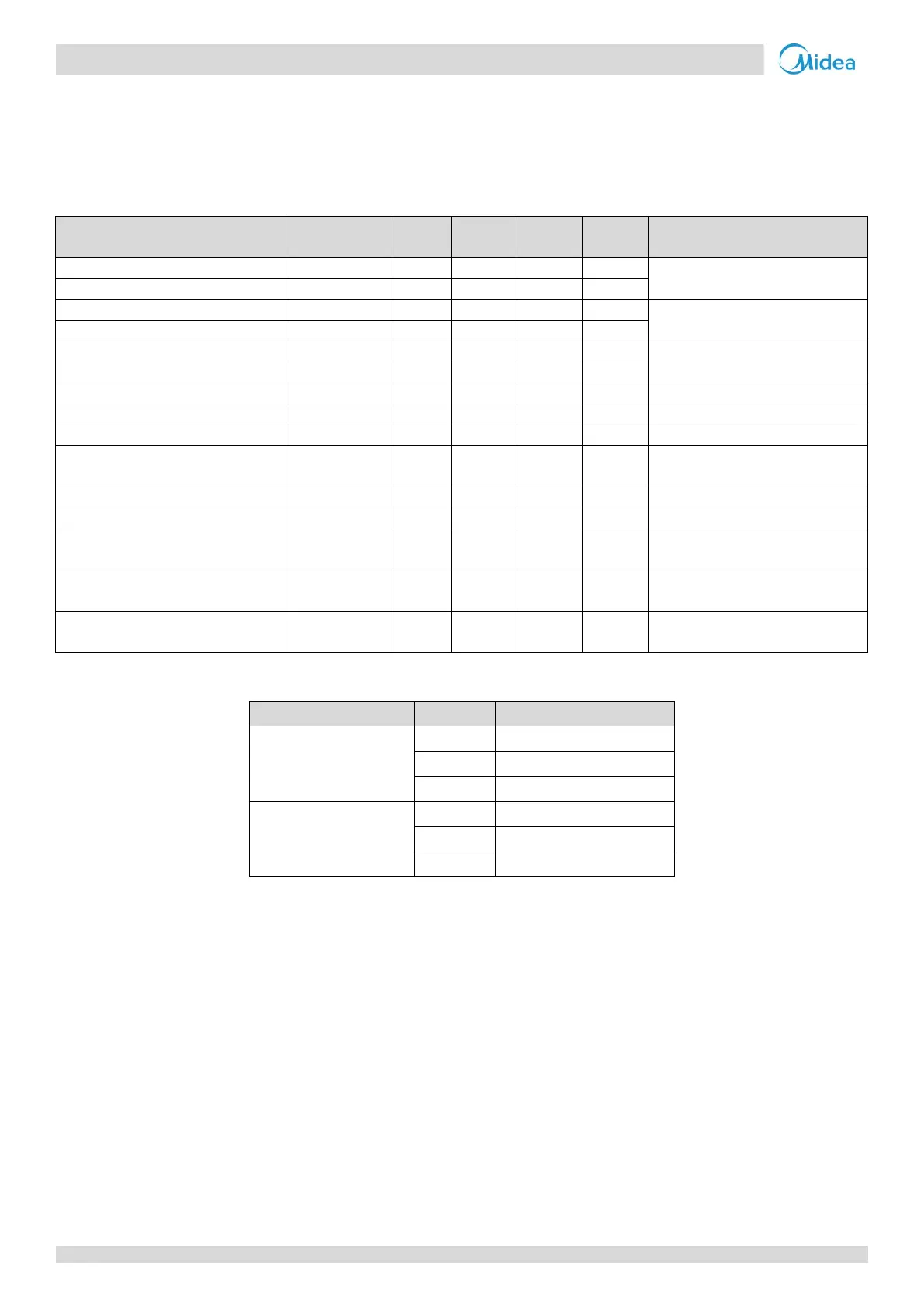
Table 3-7.5: Outdoor unit component control during defrosting operation
Component
Wiring diagram
8-12HP 14-16HP 18-28HP 30-32HP Control functions and states
● ● ● ●
Fixed frequency
● ●
● ● ● ●
Off
● ●
Electronic expansion valve A
● ● ● ●
Position 480 (steps)
Electronic expansion valve B
● ● ●
Electronic expansion valve C
● ● ● ●
● ● ● ●
Solenoid valve (oil balance)
● ● ● ●
Solenoid valve (fast defrosting (in
heating) and unloading (in cooling))
SV5 ● ● ● ● On
Solenoid valve (EXV bypass)
● ● ● ●
Solenoid valve (indoor units bypass)
●
●
Solenoid valve (inverter compressor
SV8A ● ● ● ● Off
Solenoid valve (inverter compressor
SV8B ● ● Off
Solenoid valve (inverter compressor
SV9 ● ● Open before compressor B startup
Table 3-7.6: Indoor unit component control during defrosting operation
Component Unit state Control functions and states
Fan
Thermo on Off
Standby Off
Thermo off Off
Electronic expansion valve
Thermo on 480 (steps)
Standby 480 (steps)
Thermo off 480 (steps)