V6 VRF 50/60Hz
47
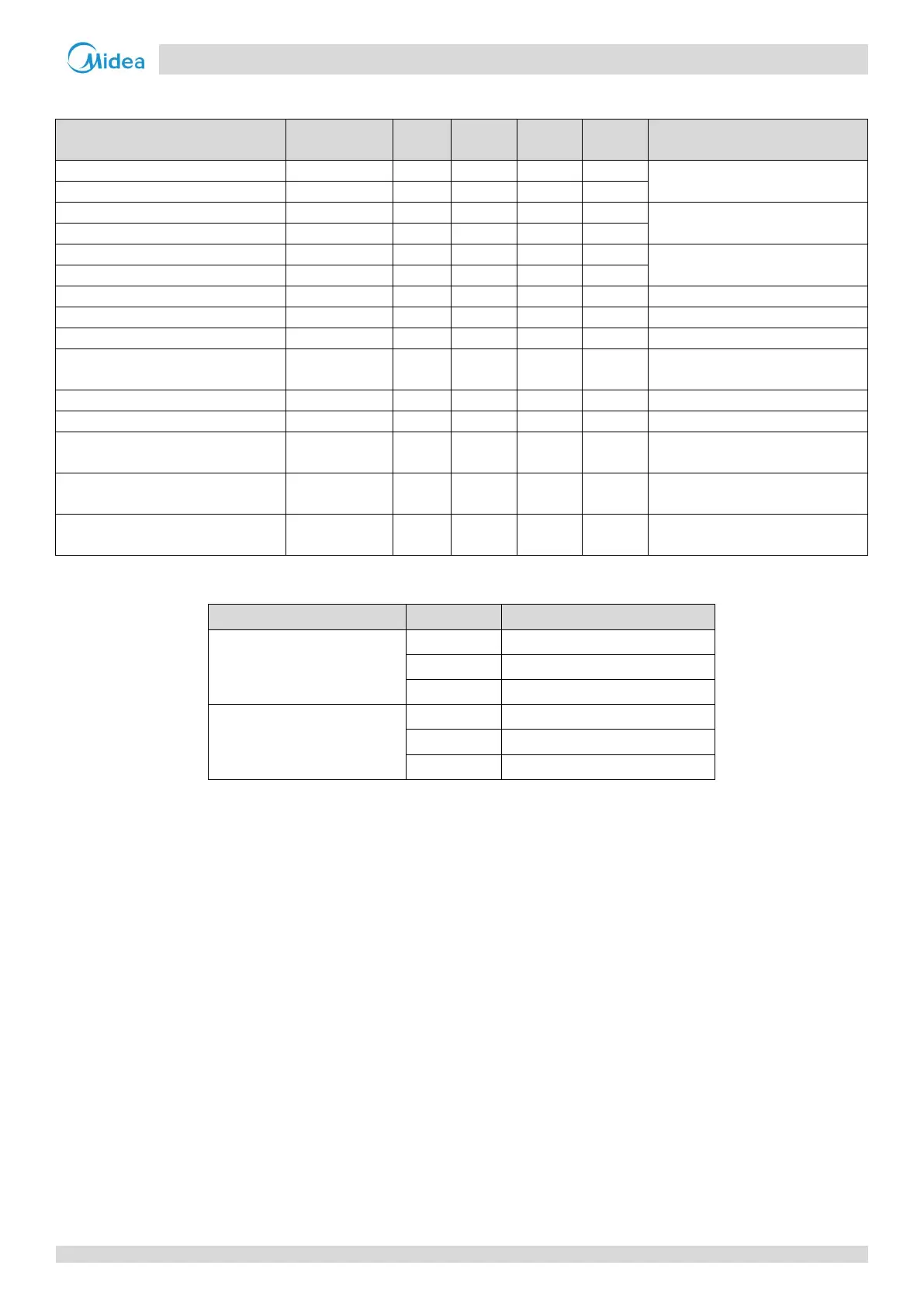
Tables 3-7.3 and 3-7.4 show component control during oil return operation in heating mode.
Table 3-7.3: Outdoor unit component control during oil return operation in heating mode
Component
Wiring diagram
8-12HP 14-16HP 18-28HP 30-32HP Control functions and states
● ● ● ●
Fixed frequency
● ●
● ● ● ●
Fan speed controlled according to
discharge pressure
● ●
Electronic expansion valve A
● ● ● ●
Position 480 (steps)
Electronic expansion valve B
● ● ●
Electronic expansion valve C
● ● ● ●
● ● ● ●
Solenoid valve (oil balance)
● ● ● ●
Solenoid valve (fast defrosting (in
heating) and unloading (in cooling))
SV5 ● ● ● ● On
Solenoid valve (EXV bypass)
● ● ● ●
Solenoid valve (indoor units bypass)
●
●
Solenoid valve (inverter compressor
SV8A ● ● ● ● Off
Solenoid valve (inverter compressor
SV8B ● ● Off
Solenoid valve (inverter compressor
SV9 ● ● Open before compressor B startup
Table 3-7.4: Indoor unit component control during oil return operation in heating mode
Component Unit state Control functions and states
Fan
Thermo on Off
Standby Off
Thermo off Off
Electronic expansion valve
Thermo on 480 (steps)
Standby 480 (steps)
Thermo off 480 (steps)