V6 VRF 50/60Hz
61
Part 5 - Electrical Components and Wiring Diagrams
Menu mode
Only master unit has the full menu functions, slaves units only have error codes check and cleaning functions.
1. Long press SW5 “MENU” button for 5 seconds to enter menu mode, and the digital display displays “n1”;
2. Press SW3 / SW4 “UP / DOWN” button to select the first level menu “n1”, “n2”, “n3”, “n4”or “nb”;
3. Press SW6 “OK” button to enter specified first level menu, for example, enter “n4” mode;
4. Press SW3 / SW4 “UP / DOWN” button to select the second level menu from “n41” to “n47”;
5. Press SW6 “OK” button to enter specified second level menu, for example, enter “n43” mode;
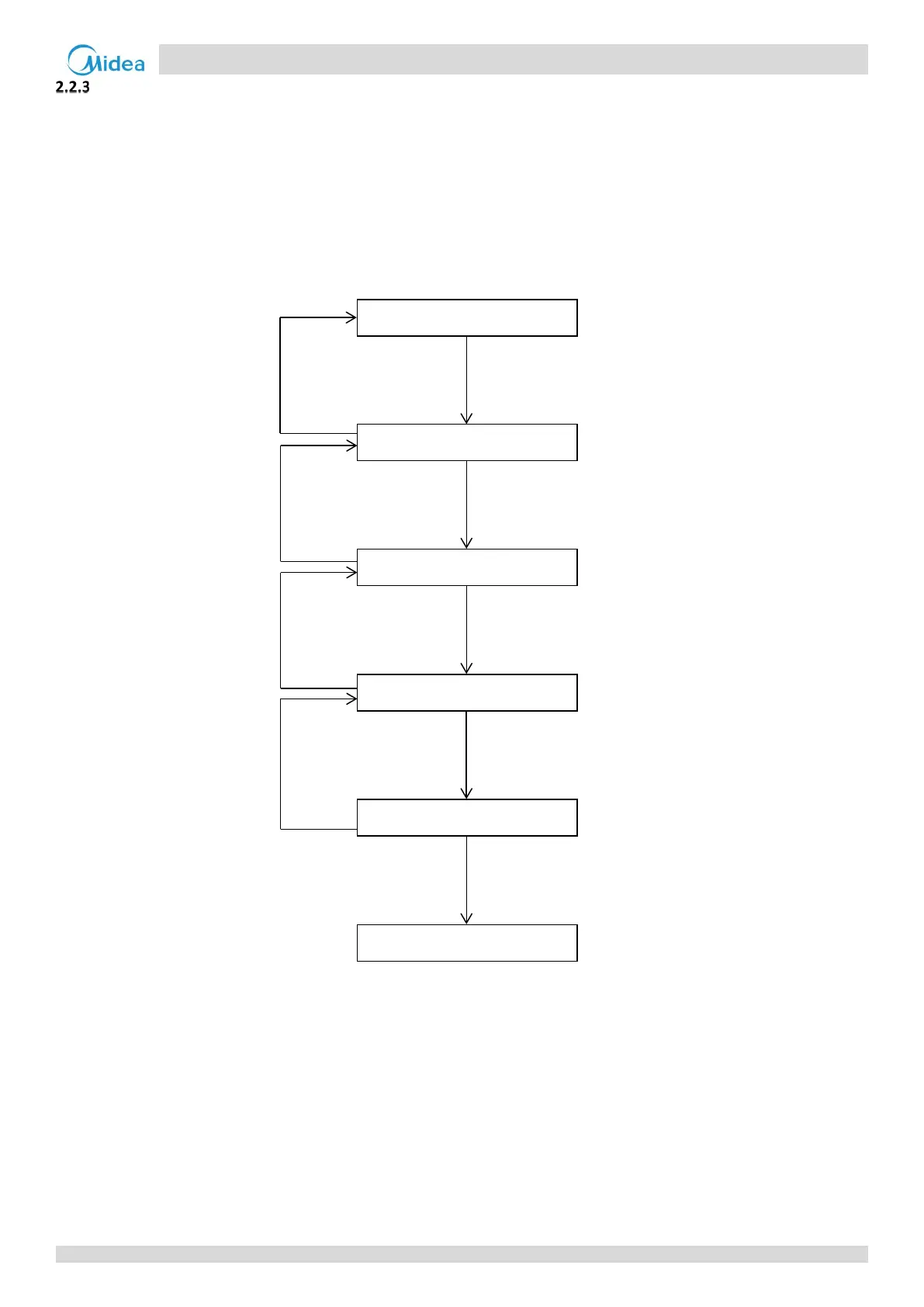
Menu mode selection flowchart:
Start
Long press SW5 “MENU”
button for 5 seconds
Digital display displays “-n1”
Press SW3 / SW4 “UP /
DOWN” button to select
the first level menu “nX”
Digital display displays “-nX”
Press SW6 “OK” button
to enter specified first
level menu “-nX”
Digital display displays “-nX1”
Press SW3 / SW4 “UP /
DOWN” button to select the
second level menu “nXY”
Digital display displays “-nXY”
Press SW6 “OK” button to
enter specified second level
menu “-nXY”
Confirm “-nXY”
Short press SW5
“MENU” button
Short press SW5
“MENU” button
Short press SW5
“MENU” button
Short press SW5
“MENU” button