V6 VRF 50/60Hz
117
Part 6 - Diagnosis and Troubleshooting
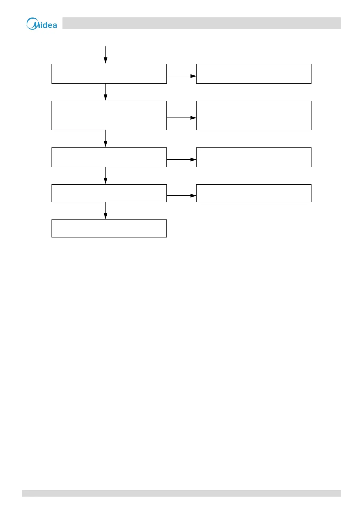
… flowchart continued from previous page
Excess refrigerant
3
Yes
Discharge part of the refrigerant. Add oil
if it leaks during discharge
No
System contains air or nitrogen
4
Yes
Flush all refrigerant then vacuum the
system and recharge the refrigerant. Add
oil to the system if it leaks
No
The high pressure side is blocked, caused
by crushed or bent pipe or blocked EXV
5
Yes
Inspect the system and fix the error
No
The condenser heat exchange is poor
6
Yes
Inspect the system and fix the error
No
Replace outdoor main PCB
Notes:
1. The high pressure/discharge temperature switch connection is port CN18 on the main PCB (labeled 1 in Figure 5-2.1 in Part 5, 2.1 “Ports”).
2. Measure the resistance between the three terminals of the high pressure and discharge temperature switch. If the resistance is of the order of mega Ohms
or infinite, the high pressure or discharge temperature switch has failed.
3. Excess refrigerant causes discharge temperature to be lower than normal, discharge pressure to be higher than normal and suction pressure to be higher
than normal. For normal system parameters refer to Table 6-3.4 and 6-3.5 in Part 6, 3.2 “Normal Operating Parameters of Refrigerant System”.
4. Air or nitrogen in the system causes discharge temperature to be higher than normal, discharge pressure to be higher than normal, compressor current to
be higher than normal, abnormal compressor noise and an unsteady pressure meter reading. For normal system parameters refer to Table 6-3.4 and 6-3.5
in Part 6, 3.2 “Normal Operating Parameters of Refrigerant System”.
5. High pressure side blockage causes discharge temperature to be higher than normal, discharge pressure to be higher than normal and suction pressure to
be lower than normal. For normal system parameters refer to Table 6-3.4 and 6-3.5 in Part 6, 3.2 “Normal Operating Parameters of Refrigerant System”.
6. In cooling mode check outdoor heat exchangers, fans and air outlets for dirt/blockages. In heating mode check indoor heat exchangers, fans and air outlets
for dirt/blockages.