V6 VRF 50/60Hz
127
Part 6 - Diagnosis and Troubleshooting
… flowchart continued from previous page
Some power wires or communication
wires of fan module are not connected
properly
Yes
Ensure power and communication wires
are connected properly
No
The fan motor is blocked or has failed
Yes
Remove obstruction or replace the fan
motor
No
The power supply is abnormal
Yes
Check the power supply equipment
No
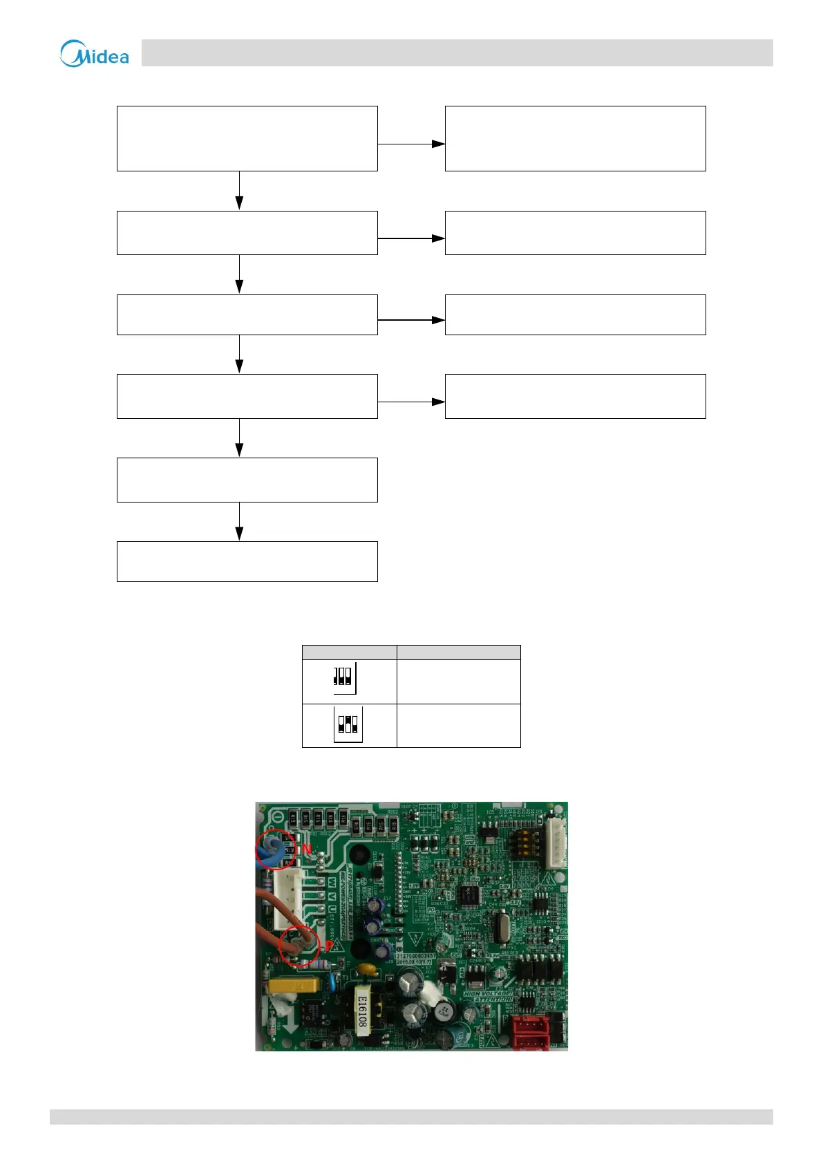
Voltage between P and N on fan module
is abnormal
2
Yes
Replace AC filter board
No
Replacing the fan module resolves the
No
Replace outdoor main PCB
Notes:
1. Fan module address is set through dial switch S7 on the fan module. The fan module location refers to the wiring diagram.
1 for master fan module
2 for slave fan module
2. The normal voltage between P and N on the fan module is 310V DC.
Figure 6-2.12: Fan module P N terminals