V6 VRF 50/60Hz
17
Part 2 - Components Layout and Refrigerant Circuits
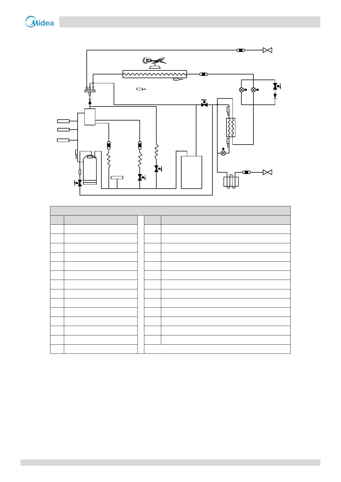
14/16HP
Figure 2-2.2: 14/16HP piping diagram
Legend
No. Parts name
No. Parts name
1 Compressor 15 Accumulator
2 Discharge temperature switch 16 Heat exchanger cooling electric control box
3 High pressure switch T3 Heat exchanger temperature sensor
4 High pressure sensor T4 Outdoor ambient temperature sensor
5 Oil separator T6A Plate heat exchanger inlet temperature sensor
6 Four-way valve T6B Plate heat exchanger outlet temperature sensor
7 Heat exchanger T7C1 Compressor A discharge temperature sensor
8 Electronic expansion valve (EXV) T7C2 Discharge pipe temperature sensor
9 Low pressure switch SV4 Oil return valve
10 Fan motor SV5 Fast defrosting (in heating) and unloading (in cooling) valve
11 Fan SV6 Refrigerant bypass EXV valve
12 Stop valve (liquid side) SV7 Refrigerant bypass indoor units valve
13 Stop valve (gas side) SV8A Compressor A vapor injection valve
14 Plate heat exchanger
2
1
15
12
9
3
4
5
6
11
10
7
14
8
8
8
13
EX
V
A
EXVB
EXV
C
E
S
C
T3
T4
T7C1
T7C2
T6B
T6A
SV8A
SV4
SV7
SV5
SV6
16