V6 VRF 50/60Hz
39
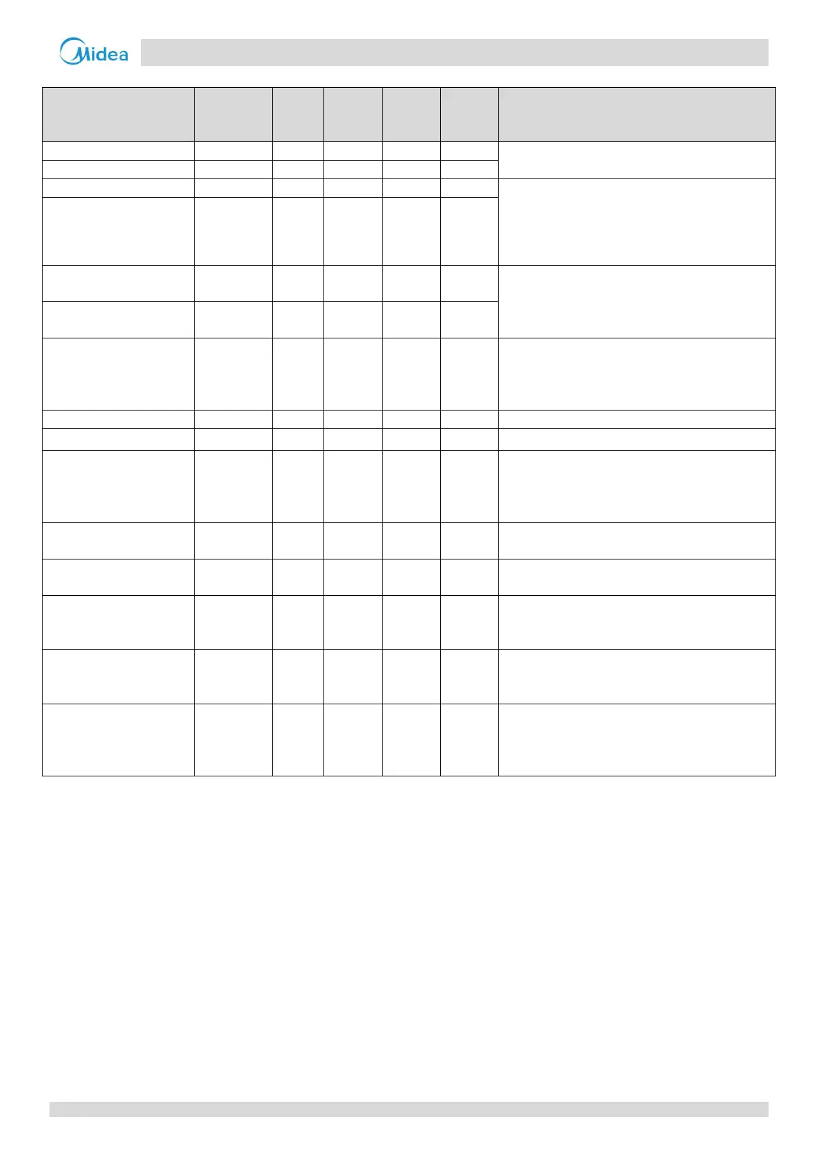
Table 3-5.2: Component control during heating operation
Component
Wiring
diagram
8-12HP 14-16HP 18-28HP 30-32HP Control functions and states
● ● ● ●
Controlled according to load requirement
● ●
● ● ● ●
Controlled according to
temperature, outdoor heat exchanger pipe
temperature
, discharge pressure and load
requirement
DC fan motor B FANB ● ●
E
lectronic expansion valve
A
EXVA ● ● ● ●
Position (steps) from 0 (fully closed) to 480 (fully
open), controlled according to discharge superheat
E
lectronic expansion valve
B
EXVB ● ● ●
E
lectronic expansion valve
C
EXVC ● ● ● ●
Position (steps) from 0 (fully closed) to 480 (fully
open), controlled according to temperature
different between plate heat exchanger inlet and
outlet
● ● ● ●
Solenoid valve (oil balance) SV4 ● ● ● ●
Open regularly
defrosting (in heating) and
unloading (in cooling))
SV5 ● ● ● ●
C
ontrolled according to ambient temperature,
discharge pressure, discharge temperature,
compressor
running frequency and discharge
superheat
S
olenoid valve (EXV
bypass)
SV6 ● ● ● ● Off
S
olenoid valve (indoor
units bypass)
SV7 ●
● Controlled according to load requirement
Solenoid valve (inverter
c
ompressor A vapor
injection)
SV8A ● ● ● ●
Controlled
according to inverter compressor A
on/off
Solenoid valve (inverter
compressor B vapor
SV8B ● ●
Controlled
according to inverter compressor B
on/off
Solenoid valve (inverter
compressor B pressure
balance)
SV9 ● ●
Open before compressor B startup and close after
compressor B running for 15 seconds. Open after
compressor B stop 10 seconds and keep open 60