V6 VRF 50/60Hz
59
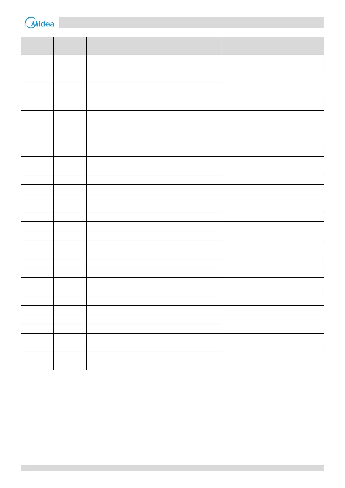
Part 5 - Electrical Components and Wiring Diagrams
Table 5-2.1: Main PCB ports
Label in
Figure 5-2.1
Port code Content Port voltage
1 CN18
High pressure switch and discharge temperature switch(es)
connections
0V or 5V DC
2 CN19 Low pressure switch connection 0V or 5V DC
3 CN4
Compressor top temperature sensor (single compressor
units) or compressor A compressor top temperature sensor
(dual compressor units) connection
0-5V DC (varying)
4 CN5
Discharge pipe temperature sensor (single compressor units)
or compressor B compressor top temperature sensor (dual
compressor units) connection
0-5V DC (varying)
5 CN3 Inverter module temperature sensor A connection 0-5V DC (varying)
6 CN3_1 Inverter module temperature sensor B connection 0-5V DC (varying)
7 CN17 High pressure sensor connection 0-5V DC (varying)
8 CN15 Inverter compressor A and B current sensor connections 0-7.8V AC (varying)
9 CN16 Reserved /
10 CN8 Plate heat exchanger inlet temperature sensor connection 0-5V DC (varying)
11 CN1
Outdoor ambient temperature sensor and outdoor heat
exchanger temperature sensor connections
0-5V DC (varying)
12 CN8_1 Plate heat exchanger outlet temperature sensor connection 0-5V DC (varying)
13 CN20 Communication port to outdoor units 2.5-2.7V DC
14 CN26 Communication port to compressor drive board 2.5-2.7V DC
15 CN27 Communication port to fan drive board 2.5-2.7V DC
16 CN25 Communication port 2.5-2.7V DC
17 CN28 Reserved /
18 CN71 EEVB drive port 0V or 12V DC
19 CN70 EEVA drive port 0V or 12V DC
20 CN72 EEVC drive port 0V or 12V DC
21 CN82 Control port of relay for AC filter board 0V or 12V DC
22 CN66-CN67 Power supply to compressor crankcase heater 220V AC
23 CN47 Four-way valve drive ports 220V AC
24 CN80 Alarm signal output port (reserved) 220V AC
25
CN40-CN46;
CN83-CN85
Solenoid valve drive ports 220V AC
26 CN30 Power input of main board
220V AC between A/B/C and N;
380V AC between A,B and C