OM-258 035 Page 46
Hardware is common and
not available unless listed.
803 159-E
1
2
3
4
5
6
7
8
9
10
11
11
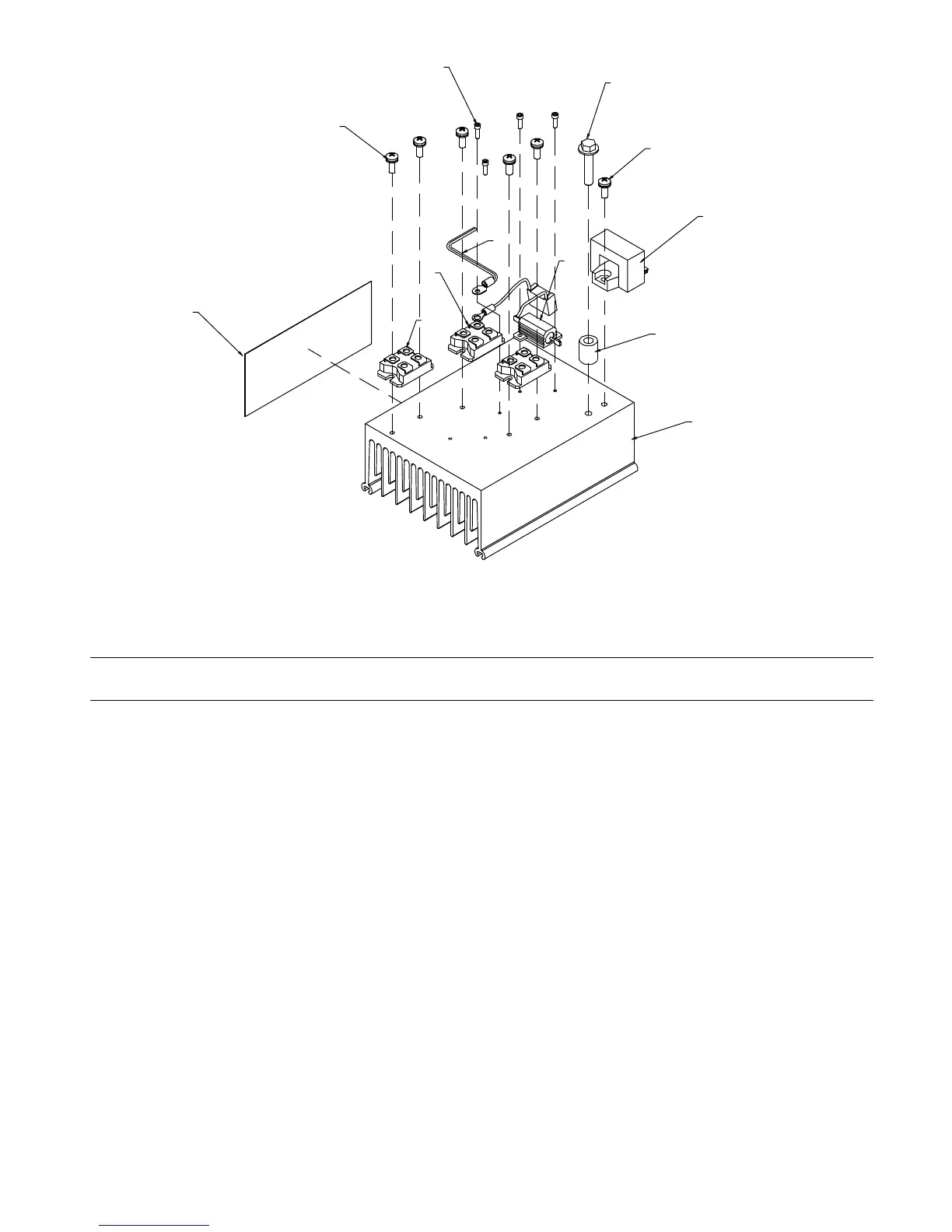
Figure 11-6. Heat Sink Assembly, Output Diode
Diagram
marking
Item
No.
Part
No. Description
Quantity
Figure 11-6. Heat Sink Assembly, Output Diode
1 205916 Heat Sink, Diode Output 1... .......... .. .............................................
2 D1,D2 223422 Kit, Diode Ultra−fast Recovery 2... .. . .. ........................................
3 SR1 201530 Kit, Diode Fast Recovery Bridge 1... ... .. .. ......................................
4 HD1 191941 Transducer, Current 1... ... .. .. .................................................
5 R1,C5 207384 Resistor/Capacitor 1... .. . .. ..................................................
6 RT1 209223 Thermistor, NTC 30k Ohm @ 25 Deg C 18in Lead 1... ... .. .. ......................
7 049611 Tubing, Cop .540 OD x .123 Wall x .687 1... ........... .. ................................
8 207932 Insulator, Heatsink 1... .......... .. ..................................................
9 108942 Screw, 250−20 x1.25 Hexwhd .61D Gr5 Pld 1... .......... .. ............................
10 602062 Screw, 004−40 x .37 Pan Hd−Phl Stl Pld Cone Sems 5... .......... .. ....................
11 207451 Screw, 008−32 x .50 Pan Hd−Phl Stl Pld Sems 7... .......... .. .........................
VRD Models only.
To maintain the factory original performance of your equipment, use only Manufacturer’s Suggested
Replacement Parts. Model and serial number required when ordering parts from your local distributor.
 Loading...