OM-258 035 Page 45
Hardware is common and
not available unless listed.
803 949-B
1
7
2
3
4
5
6
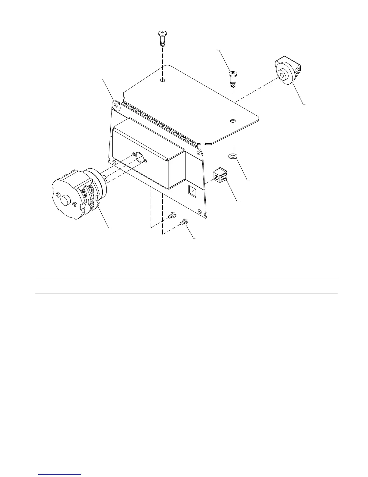
Figure 11-5. Relinking Switch And Door Assembly
Description
Part
No.
Dia.
Mkgs.
Item
No.
Figure 11-5. Relinking Switch And Door Assembly
Quantity
1 +217252 Door Assy, Relinking 1... ......... .. .................................................
228702 Label, Switch Position 208−230/400−460 VAC (208−230/400−460 Models) 1................ .. ..
228675 Label, Switch Position 220−230/460−575 VAC (220−230/460−575 Model) 1................ .. ...
221462 Label, Caution Operating Link Switch Etc 1................ .. ...............................
2 217647 Switch, Rotary 3 Posn 4P 32A 600V 180 Deg (Spl) 1... .......... .. ......................
3 209554 Screw, KA 35 x 8 Pan Hd−Phl 2... .......... .. ........................................
4 221573 Nut, Speed Snap−in 1/4 Turn 2... .......... .. .........................................
5 221575 Retainer, Nylon Push−On 2... .......... .. ............................................
6 221574 Screw, 1/4 Turn Oval Hd−Phl 2... .......... .. .........................................
7 230485 Knob, Switch 1... .......... .. .......................................................
+When ordering a component originally displaying a precautionary label, the label should also be ordered.
VRD Models only.
To maintain the factory original performance of your equipment, use only Manufacturer’s Suggested
Replacement Parts. Model and serial number required when ordering parts from your local distributor.
 Loading...