OM-263 657 Page 33
7-3. Welding Power Source And Remote Diagnostics Help Codes
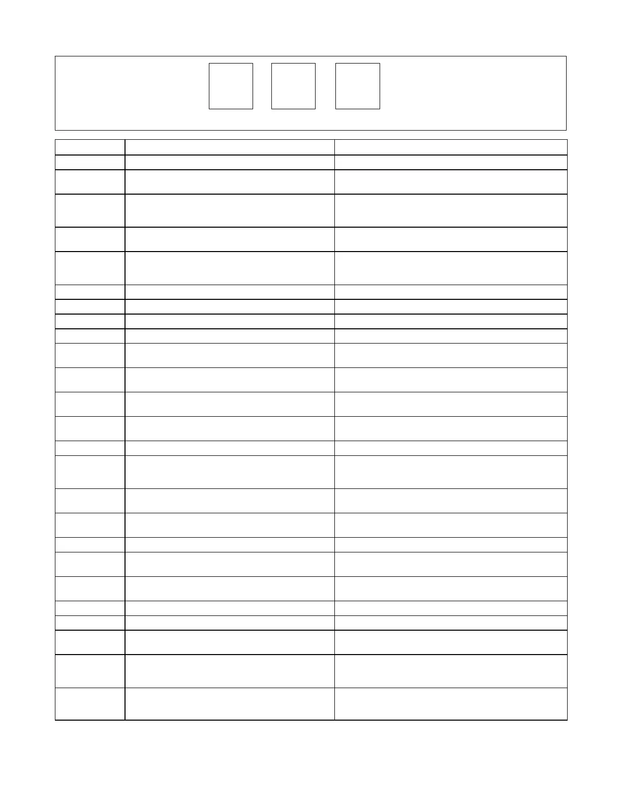
H1
Display Example
0
Display Code Fault Description
H01 Primary Transformer Over Current Indicates a malfunction in the primary power circuit.
H02 Secondary Thermistor Malfunction Indicates the left side thermal protection circuitry is
malfunctioning.
H03 Secondary Circuit Over Temperature Indicates left side of unit has overheated. Unit has shutdown to
allow fans to lower left side temperature. Operation will continue
after unit is within normal temperature range.
H04 Primary Temperature Sensor Malfunction Indicates the right side thermal protection circuitry is
malfunctioning.
H05 Primary Circuit Over Temperature Indicates right side of unit has overheated. Unit has shutdown
to allow fans to lower right side temperature. Operation will
continue after unit is within normal temperature range.
H06 Current Foldback Indicates operation at maximum input current..
H08 Output Over Voltage Malfunction Output voltage exceeded 100 VDC for more than 1/2 second.
H12 Precharge Incomplete Precharge did not complete in allotted time.
H13 Internal Voltage Malfunction System cannot measure output voltage.
H16 PC2 Temperature Sensor Malfunction Indicates thermal protection circuitry on the Process Control
board is malfunctioning.
H17 PC2 Over Temperature Indicates PC2 has overheated. Unit has shutdown to allow fans
to lower temperature.
H18 PC3 Temperature Sensor Malfunction Indicates thermal protection circuitry on the System Power
board is malfunctioning.
H19 PC3 Over Temperature Indicates PC3 has overheated. Unit has shutdown to allow fans
to lower temperature.
H20 PC2 Power Supply Low Indicates the control supply on PC2 is malfunctioning.
H21 Primary Input Line Voltage Malfunction Indicates input primary line voltage is too low.
Primary line voltage must be at least 90% of specified nominal
voltage.
H22 Boost Fault Indicates the boost circuitry on the right side of unit is
malfunctioning.
H26 Button Stuck On Power Source Indicates button is stuck on the power source upon start up.
Fault will clear when button is released.
H27 Polarity Switch Fault Indicates the relay circuitry (W1, W2) is malfunctioning.
H30 Stuck Contactor TIG/Stick Indicates a stuck remote contactor in either Stick or TIG pro-
cess.
H32 Accessory Temperature Sensor Malfunction Indicates the thermistor in the attached FieldPro accessory is
malfunctioning.
H33 Accessory Over Temperature Indicates the attached FieldPro accessory has overheated.
H96 PC7 Communication Malfunction Indicates internal communication malfunction to PC7.
H97 PC1 Communication Malfunction Indicates internal communication from primary power circuitry
to secondary power circuitry on PC1.
H98 Serial Communication Loss Indicates serial communication was initially made and is now
malfunctioning. May appear normally during firmware updates.
Communication between PC1 and PC5 malfunction.
H99 Serial Communication Malfunction Indicates serial communication is malfunctioning. May appear
normally during firmware updates. Communication between
PC1 and PC5 malfunction.