OM-263 657 Page 34
7-4. Feeder Diagnostics Help Codes
The FieldPro Feeder does not display the same help codes as the power source. Error conditions are indicated by a “HLP” message on the display, or
by the blinking of the Red LED on motor board PC1. To view the Red LED, turn off the power source, remove the wrapper, and turn power source back
on. The Red LED blinks in a 2.5 second cycle. The number of blinks in this period indicates the type of error. If an error condition does not exist on the
motor board, the Red LED is on steady.
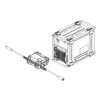
H1
Display Example
0
Display
Code
Red LED On PC1 Fault Description
H11 1 Blink Communication Error
This error occurs 2.5 seconds after a loss
of communication between the motor
board and meter board. The operator may
continue to weld with this error present.
The error may be cleared by turning the
power off, waiting a minimum of 2 seconds,
and turning power back on.
H12 2 Blinks Trigger Error
This error occurs if the operator has fed
approximately 35 ft (10.7 m) of wire without
striking an arc, or if the welding wire is
shorted during a welding operation and
switch DIP4 on the front panel board is de-
pressed toward the OPEN position. The
error may be cleared by releasing the gun
trigger.
H14 4 Blinks (Constant Blinking) Motor Overload
Indicates that the motor has been drawing
too much current for too long. To remedy,
reduce the wire feed speed or the wire
feeder torque load/duty cycle. The error
may be cleared by turning the power off,
waiting a minimum of 2 seconds, and turn-
ing the power back on.
H15 3 Blinks Bus Bar Overheating
Indicates the arc is drawing too much cur-
rent for too long. To remedy, reduce the
weld amperage or duty cycle.
7-5. Troubleshooting Welding Power Source
Trouble Remedy
No weld output; unit completely in−operative Place line disconnect switch in On position (see Section 5-5).
Check and replace line fuse(s), if necessary*.
Check for proper input power connections (see Section 5-5).
No weld output; meter display On. Check, repair, or replace RHC-14 remote control.
Unit overheated. Allow unit to cool with fan ON (see Section 4-3).
Check ammeter help displays.
Erratic of improper weld output. Use proper size and type of weld cable.
Clean and tighten all weld connections.
Check volt sense lead. Straighten any coiled cables.
When remote control is connected to unit output
is always on.
Check RHC-14 remote control switch and potentiometer resistances.
*Have a trained and qualified service technician check and replace line fuse(s).