© 2009 MIMAKI ENGINEERING CO.,LTD.
1.1.6 P.1
1
2
3
4
5
6
7
8
R.1.0
Maintenance Manual > Operating Principle > Basic Operation > Operation for Connecting the Heads
Model CJV30/TPC Issued 2008.08.04 Revised F/W ver. 1.00 Remark
1.0
1.1.6 Operation for Connecting the Heads
Processing sequence
Separation of the cut head Connection of the print head
Separation of the print head Connection of the cut head
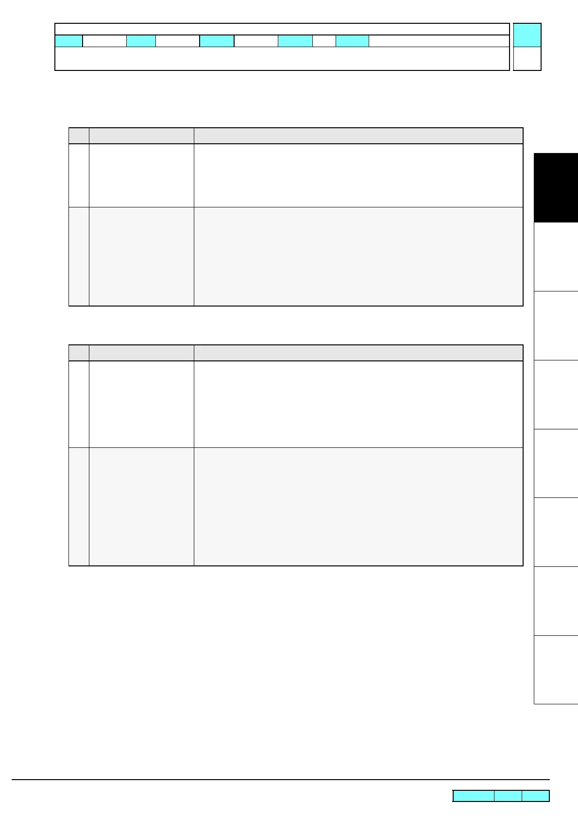
Step Processing Description
1 Separate the cut head. 1. After moving the cut head carriage to the left end and turning on the clamp solenoid, check
the position of the cut head by the cut head connection sensor.
• In the malfunction, [ERROR170 CUTTER LOCK] is displayed.
2. After checking the position, turn off the clamp solenoid and lock up the cut head.
3. Move the head connecting unit to the right and separate the cut head.
2 Connection of the print head 1. Move the head connecting unit to the right end.
2. After checking a Y origin, connect the print head to the cut head.
• In the malfunction, [ERROR170 CUTTER LOCK] is displayed.
3. Turn on the print head solenoid and unlock the print head.
4. Detect a Y origin again and cap the print head.
5. Turn off the print head solenoid and lock up the print head.
• When starting to plot, turn on the print head solenoid and unlock the print head, then
move the print head.
Step Processing Description
1 Separate the print head. 1. After turning on the print head solenoid, move the print head carriage and check a Y origin.
• In the malfunction, [ERROR170 PRINT HEAD LOCK] is displayed and the system
goes down.
2. After checking the Y origin, move the print head back to the capping position and carry
out capping.
3. Turn off the print head solenoid and lock up the print head.
4. Move the head connecting unit to the left and separate the print head.
2 Connection of the cut head 1. Move the head connecting unit to the left end.
2. Connect the cut head to the head connecting unit and after turning on the clamp solenoid,
check the position of the cut head by the cut head connection sensor.
• In the malfunction, [ERROR170 PRINT HEAD LOCK] is displayed and the system
goes down.
3. Detect a Y origin again and cap the print head.
4. Move the head connecting unit back to the standby position of the cut head carriage and
turn off the clamp solenoid, then lock up the cut head.
• When starting the cutting operation, turn on the clamp solenoid and unlock the cut
head, and then move the cut head.
 Loading...


