© 2009 MIMAKI ENGINEERING CO.,LTD.
6.4.11 P.1
1
2
3
4
5
6
7
8
R.1.1
Maintenance Manual > Disassembly and Reassembly > Drive System > Clamp Assy
Model CJV30/TPC Issued 2008.08.04 Revised 2008.09.17 F/W ver. 1.20 Remark
1.1
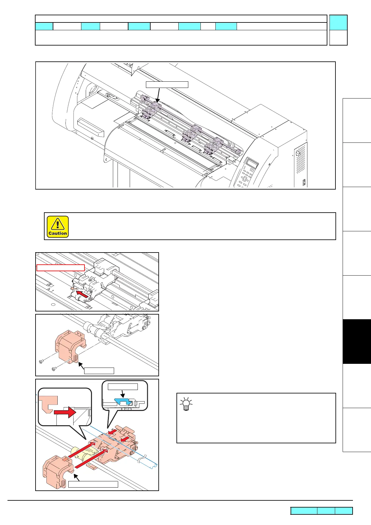
6.4.11 Clamp Assy
Work procedures
1. Remove the CY cover F.
2. Lower the clamp lever and set the lever below the clamp assy to
the left.
3. Remove the cam holder from the rear of the printer and clamp
assy.
4. Reverse the disassembly procedure for reassembly.
Be sure to turn off the main circuit breaker to prevent unexpected movements of the printer.
When mounting the clamp assy, place the front right
and left hooks on the PR guide and mount it horizon-
tally so that the right and left cam holder hooks can
be placed in the groove of the clamp assy.
For easy work, set clamp pressure to Low by manual
operation and lower the clamp lever.
 Loading...


