– 1.4 –
1-4. Names of parts
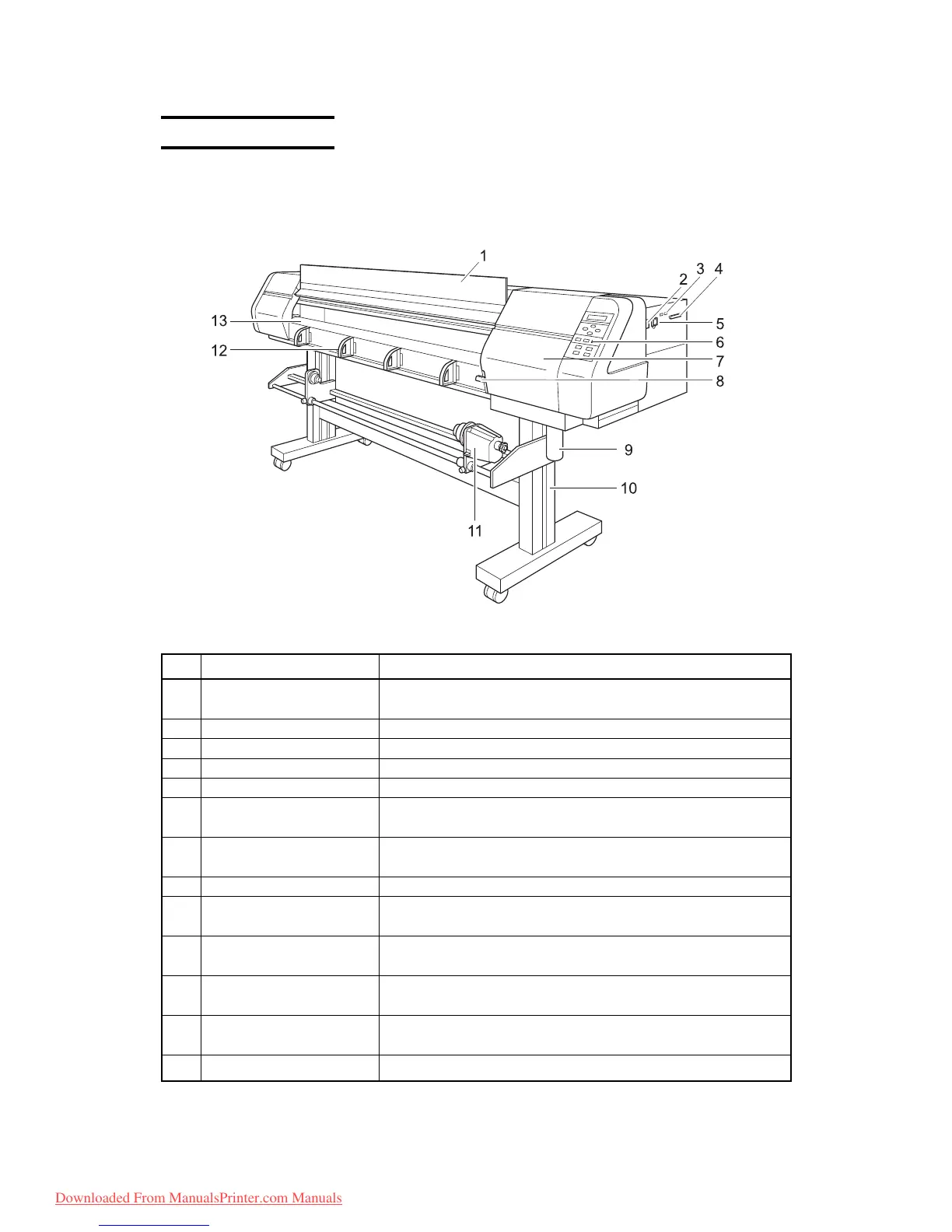
1-4-1. Front face
Name Function
1 Front cover It is opened when setting medium or taking a corrective measure against
a medium jam.
2 Power switch It turns on/off the power to the device.
3 IEEE-1394 connector A 400M bps interface connector compatible with IEEE-1394.
4 Parallel connector Bi-directional parallel interface connector (complies with IEEE1284)
5 AC inlet The power cable is connected to the AC inlet.
6 Operation panel This panel has the operation keys required for operating the device
and the LCD for displaying set items, etc.
7 Maintenance cover This is the carriage cover. During maintenance of the station, open it by
loosening the screws.
8 Clamp lever It is made to go up-down the pinch roller for holding medium.
9Waste ink tank Waste ink gathers in this tank. One waste ink tank is provided on each
side of the device.
10 Stand It supports the main unit. It is provided with casters that are used to
move the device.
11 Take-up device It supports to wind up the roll medium printed, and have the operation
named FORWARD / OFF / REVERSE.
12 Medium support It supports to send the medium smoothly. It has merit for preventing
rises of hard medium such as canvas.
13 Platen It puts out the medium as it is plotted on.
Downloaded From ManualsPrinter.com Manuals
 Loading...


