-5.20-
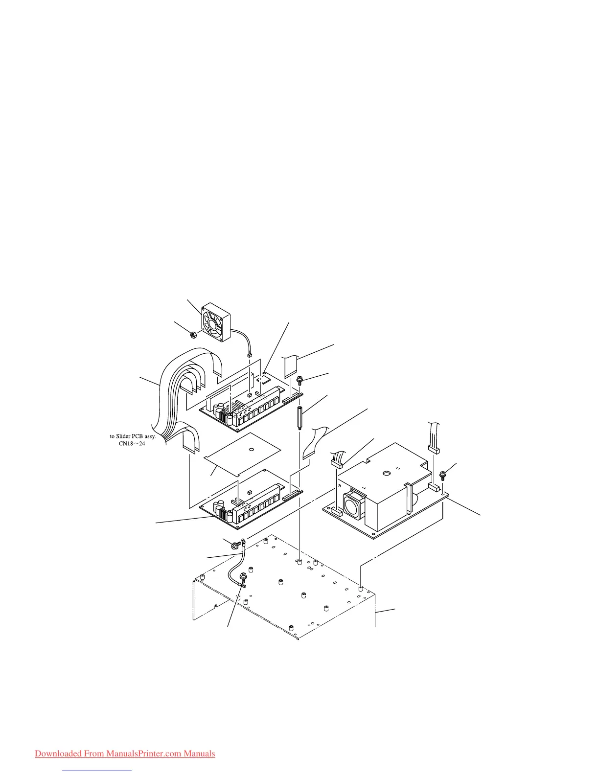
<HDC-4 Head PCB assy.>
1) Turn OFF the power supply switch, remove the electrical unit cover.
2) Remove all of the cables connected to the HDC-4 Head PCB assy.
3) Remove the screw (P3 x 8SMW) and remove the HDC-4 Head PCB assy.
Follow the procedure given below to replace the HDC-2 Head PCB assy.
1) Remove the Protection plate.
2) Remove all of the cables connected to the HDC-2 Head PCB assy.
3) Remove the screw (SQ-60) and remove the HDC-2 Head PCB assy.
[Assembling procedure]
• Assembly is reverse of disassembly.
to Main PCB assy.
CN19
to Main PCB assy.
CN1
to Power switch
To Main PCB assy
PN18
Cartridge cover R
HDC-4Head PCB assy.
Main FPC1 assy.
P3 x8SMW
Spacer
Main FPC2 assy.
DC cable assy.
Cooling fan motor assy.
HDC FPC assy.
Nut
FG cable assy.
Power supply assy.
P4 x8SMW
P4 x8SMW
Plotection
Plate
HDC-2Head PCB assy.
P3 x8SMW
Downloaded From ManualsPrinter.com Manuals
 Loading...


