4-4 Product Principle
4.2.2 CW Board
Front-end
analog
motherboard
Probe board
Low
pass
filter
ADC
Q channel
I channel
Low-
pass
filter
ADC
LNA
Demodulati
on circuit
LNA
Signal processing board
Pencil probe
CW pulse
transmitting
circuit
Board-to-board connect socket
Board-to-board
connect socket
Board-to-board
connect socket
Digital echo
Control signal
A+12V/A-12V/A+19V/A+5V7/A-
5V7/A+4V/A+3V3/A+2V5/A+1V8
Clock
CW board
Demodulati
on circuit
Adder
(multiplex
composition )
Adder
(multiplex
composition )
AD collection after
demodulation
AD collection after
demodulation
Front end
power board
Receiving
board
FPGA
Communication motherboard
Board-to-board connecting socket
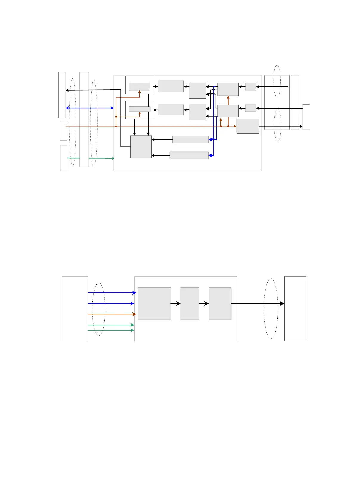
Fig 4-4 Schematic Diagram of CW Board
Function (Only phased array probe and pencil probe are supported):
Realizing transmitting, receiving and beam forming of CW signal;
Parameter control and mode switching in CW mode;
Data output by beam former are output to DSP board, and then
upload to CPU module for CW image processing via the upload logic chip.
The system can communicate with the CW board via the communication control bus.
4.2.3 Transmission Board
Communi
cation
mother-
board
High-
voltage
pulse
output
circuit
Drive
circuit
Transmitting
control
FPGA
Transmission board
64-channel
transmitting
Communication
control bus
Scanner time
sequence
Clock
4-channel
PHV
A+12V/A-12V
/A+4V2/A+3V3
/A+1V8
Board-to-board
connect socket
Front
-end
analog
mother
board
Board-to-board
connect socket
Fig 4-5 Schematic Diagram of Transmission Board
Hardware structure of the transmission board is shown as the figure above. Realize 128-channel
transmission pulse. For 192/256-elemented probe, the high voltage switching is realized in the
housing of the probe. There are two transmission boards: board A and board B, each board takes
charge of 64-channel transmission pulse. Board A and board B are the same, so both of them are
named transmission board. Only difference is the position.
Function:
Generate 64-channel transmission waveform according to the scanning sequence and
control parameter.
The 64-channel transmission waveforms are drove into 64-channel high-voltage
transmission pulses by the drive circuit.
 Loading...


