Product Principle 4-25
4.8.6 System power on control
Digital board
12VSTB
EDC_+12V_EN_N
EDC_+12V_OK_N
12VSTB
EDC_+12V_EN_N
EDC_+12V_OK_N
EDC_12V EDC_12V
PWR_BTN_N
S3#
S4#
PWRBTN#
Battery port Battery port
EDC_12V
PWR_OK
5VSTB
DC-DC power module
Control panel
power button
AC-DC
power
board
Battery
unit
CPU module
5VSTB
S4#
S3#
PWRBTN#
PWR_OK
D12V
S3#
S4#
PWRBTN#
5VSTB
PWR_OK
Back-end
mother
board
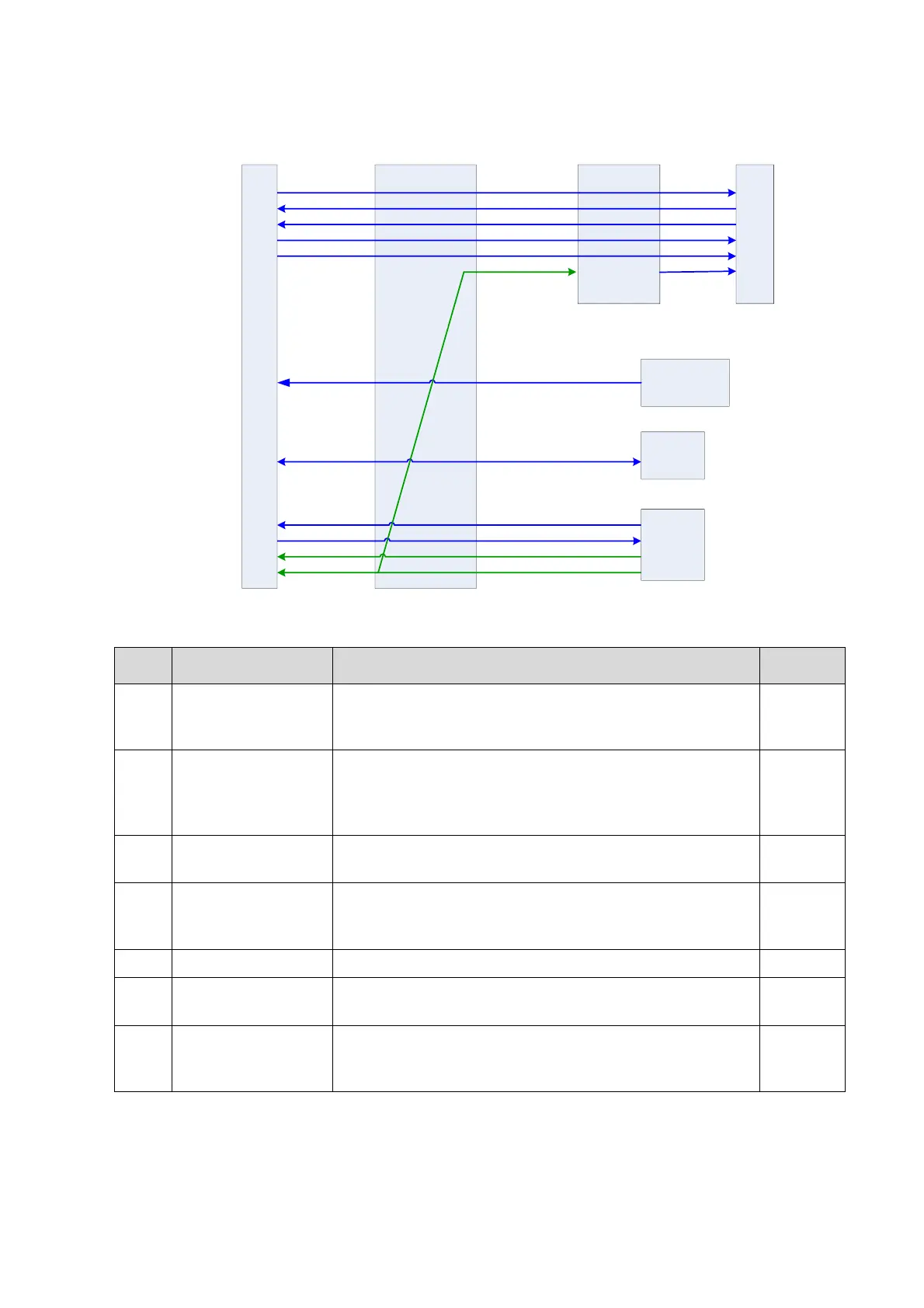
Fig 4-29 System power on control
The related control signals:
The pulse signal, which is generated by the control panel
power button, is transferred to the CPU module through
power management FPGA, for system being turned on.
CPU module output, effective means CPU system is in
standby mode (S4# is high), the power management
FPGA controls 5VSTB, in system standby mode, it is
powered.
CPU module output, effective means CPU system is in
hibernation mode.
Power management FPGA output to AC-DC power
board, controls the power of power module except
5VSTB_CPU and 3V3STB, low level is effective.
12V power finished signal from AC-DC power board
From power management FPGA to CPU module, means
12V power is finished.
From AC-DC power board to DC-DC module, for
generating 3.3VSTB and 5VSTB, if there is AC input, the
power will keep effective.
The main system is completely AC powered, the battery only to be used for standby mode, the
battery provides 12VSTB if there is no AC input, the system can’t be turned on.
Only if there is AC input, 12VSTB power will generate 5VSTB and 3.3VSTB.