9. Safety system
MiR250 User Guide (en) 07/2020 - v.1.2 ©Copyright 2020: Mobile Industrial Robots A/S. 97
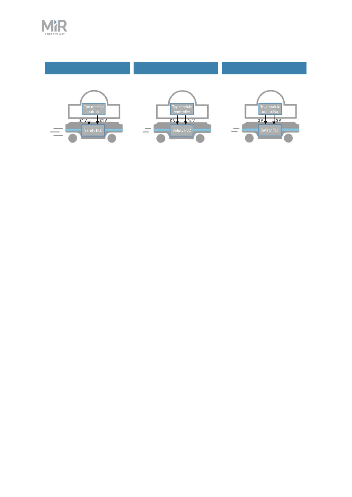
Default speed Reduced speed Reduced speed
Figure 9.9. The robot drives at its default speed only when both inputs are 24 V. If either or both pins are 0V,
the robot drives at 0.3 m/s.
Pins 4 in interfaces Aand B of the Auxiliary safety functions are used for the Reduced speed
function.
9.10 Robot computer
The robot computer is connected to the safety PLCvia an Ethernet cable. The safety PLC
sends all of the statuses of its various inputs to the robot computer so the information can be
sent to the robot interface. This enables you to identify which part of the safety system may
be causing a Protective or Emergency stop.
Additionally, the robot computer sends the current robot state to the power board which
regulates the indicator lights, ensuring that the status lights indicate which state the robot is
in.
9.11 Light indicators and speakers
The robot uses two types of light indicators to let people in the environment know what the
robot is currently doing or planning to do.
• Status lights
An LED light band on all four sides of the robot uses colors and light motion patterns to
signal the current status of the robot.
 Loading...


