Instructions for Use SonaStar Ultrasonic Surgical Aspiration System
IFU-601 Rev T March 2023 Page 27 of 73
2. Irrigation Pump - peristaltic pump used to control flow of irrigating solution to the handpiece
tip. The irrigation tubing is connected to the IV tubing, and routed clockwise around the pump,
and to the handpiece. The pump provides flush flow to the handpiece and preset flow during
vibration with minimum flow for two minutes upon release of the footswitch.
Depressing the flush button allows flush and temporarily pinches off the suction line to allow
maximum flow to “flush” the surgical site.
The irrigation pump operates at >15cc/min. during COAG function.
3. Handpiece Connector - connector for attaching the plug end of the handpiece cable to the
console.
4. Tissue Release Valve - pinch-off valve through which suction tubing is routed. Closes for ½
second when the footswitch is released, shutting off suction to the tip. This valve is also
activated during flush mode to allow irrigation delivery to the operative site without being
immediately aspirated.
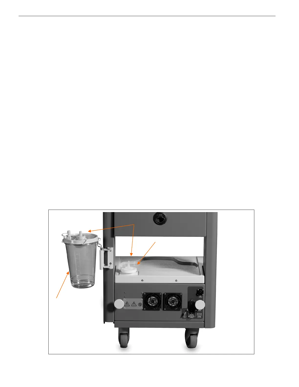
5. Suction Canister – mounted on securing bracket for collection of aspirated fluid and tissue. It is
connected to the aspiration filter assembly via a vacuum hose from the suction port. From the
patient port of the canister it is connected via a vacuum hose to the handpiece.
6. Aspiration Filter Assembly – external (visible) and internal vacuum filters.
See Section 8.6, Periodic Maintenance.
7. Primary Suction Tubing – Primary vacuum connections from the unit to
the "vacuum" port on
the suction canister.
Figure 4-2: Lower Rear View Features
7
6
5