Instructions for Use SonaStar Ultrasonic Surgical Aspiration System
IFU-601 Rev T March 2023 Page 39 of 73
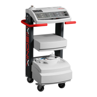
Figure 5-5a: Exploded View of SS Handpiece Parts
1: Handpiece 3: Short Front Housing (CFSM6-H185)
2: Short Probe 4: Silicone sleeve
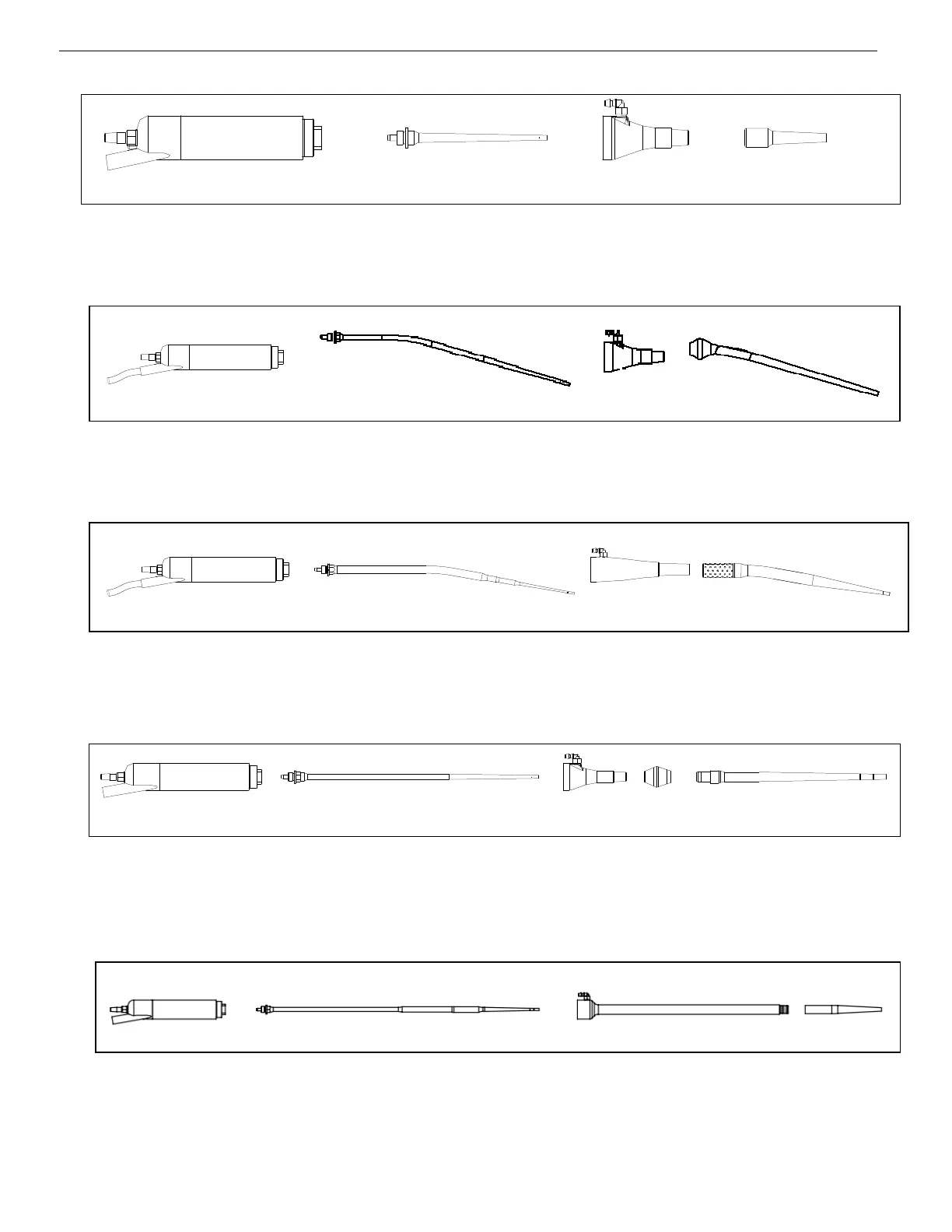
Figure 5-5b: Exploded View of SS Handpiece Parts with Long Curved Plus Probe
1: Handpiece 3: Short Front Housing (CFSM6-H185)
2: Long Curved Plus Probe 4: Silicone sleeve
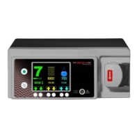
Figure 5-5c: Exploded View of SS Handpiece Parts with Precision, Micro and Standard Long
Curved Probe
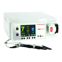
Figure 5-5d: Exploded View of SS Handpiece Parts with Deep Access Probe
1: Handpiece 4: Silicone Joint
2: Deep Access Probe 5: Rigid Sleeve
3: Short Front Housing (CFSM6-H185)
Figure 5-5e: Exploded View of SS Handpiece Parts with Laparoscopic Probe
1: Handpiece 3: Laparoscopic Rigid Sheath (CFSM6-H190)
2: Laparoscopic Probe 4: Silicone Tip
3: Long Front Housing (CFSM6
4: Long Curved Silicone Sleeve
1
2
3
4
1
2
3
4
1 2 3
4
2
3
4
5
1
2
3
4