Instructions for Use SonaStar Ultrasonic Surgical Aspiration System
IFU-601 Rev T March 2023 Page 38 of 73
5.3.4 Housing Assembly, Curved Extended Handpiece (CE)
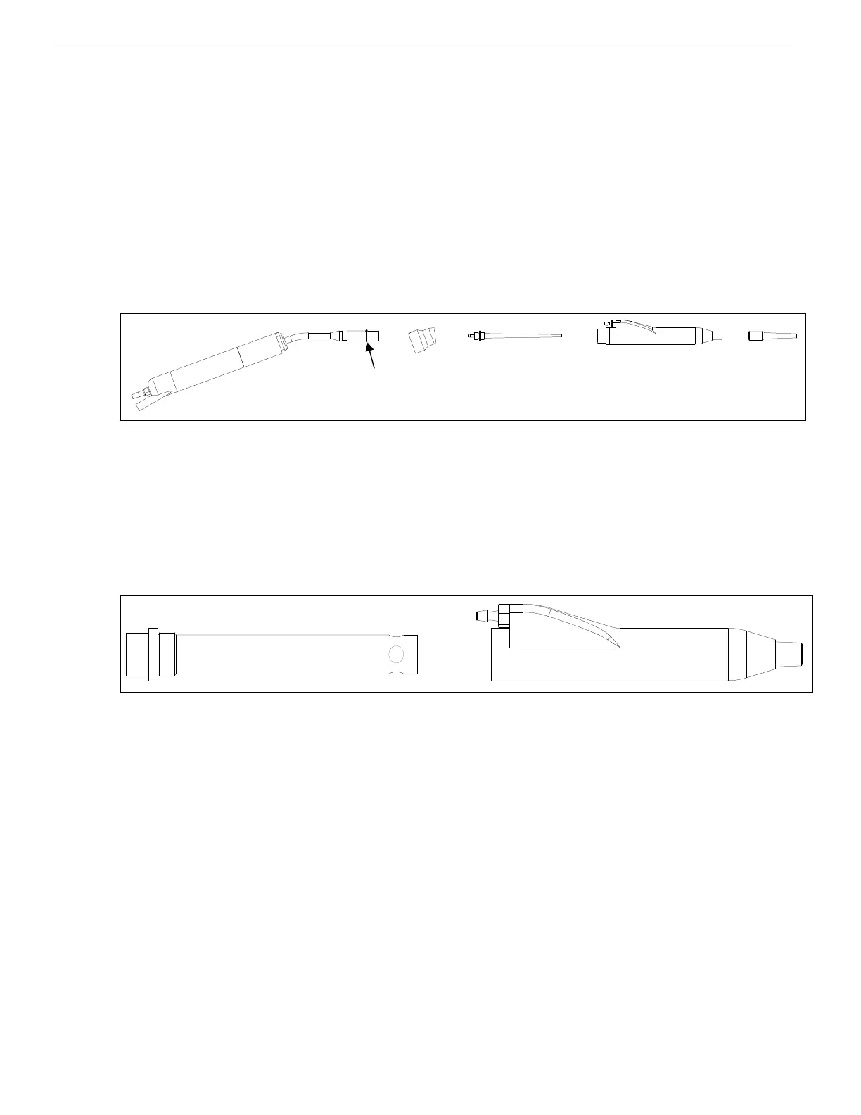
1. Remove the handpiece from the fixture. Install the Mid-Housing by screwing onto the
handpiece. Then snap the silicone elbow onto the Mid-Housing and align with the notch in
the silicone elbow. See Fig. 5-3.
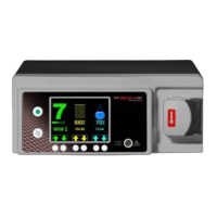
2. Screw together the inner and outer sleeves that make up the Housing Tip Assembly. See
Fig. 5-4.
3. Install rigid Housing Tip Assembly (push) onto the silicone elbow, until the silicone elbow
makes contact with the shoulder of the rigid Housing Tip Assembly.
4. From the Procedure Tray install the silicone sleeve onto the rigid Housing tip Assembly.
The handpiece is ready for system setup.
Figure 5-3: Exploded View of CE Handpiece Parts
2: Mid-Housing
Figure 5-4 below)
Figure 5-4: CE Front Housing Assembly
5.3.4 Housing Assembly, Short Straight Handpiece (SS)
1. For SS screw the plastic front housing cap onto the handpiece.
See Fig. 5-5a, 5-5b, 5-5c and 5-5d.
2. From the Procedure Tray install the silicone sleeve onto the rigid Housing tip Assembly.
The handpiece is ready for system setup.
(For 5-5d only): From the Procedure Tray install the silicone joint onto the end of the short
front housing. Slide rigid sleeve into silicone joint. The handpiece is now ready for system
setup.
Outer Inner
1
2
3
4
5 6
7
8


 To Next Page