Instructions for Use SonaStar Ultrasonic Surgical Aspiration System
IFU-601 Rev T March 2023 Page 3 of 73
Table of Figures
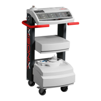
SonaStar Ultrasonic Surgical Aspiration System
ntegrated IR Receivers on
Integrated IR Receiver and Remote IR Receiver
Matching Wireless Footswitch and Receiver Frequency Codes
(A) Curved Extended (CE) and (B) Short Straigh
Placing SS & CE Handpieces in the Counter Wrench
Exploded View of CE Handpiece Parts
Exploded View of SS Handpiece Parts
Handpiece Parts with Long Curved Probe
SS Handpiece Parts with Pricision, Micro and Standard Long Curved
Probe
Exploded View of SS Handpiece Parts with Deep Access Probe
Open Irrigation Pump Gate
Routing of Irrigation Tubing
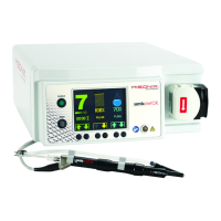
Console with Force 2 Electrosurgical Generator
Monopolar COAG Interface Schematic
Monopolar Handpiece Cable Attached to Endcap Receptacle
External Filter Installed