112
LCD PC E
LCD PC E
-
-
8590 MAINTENANCE
8590 MAINTENANCE
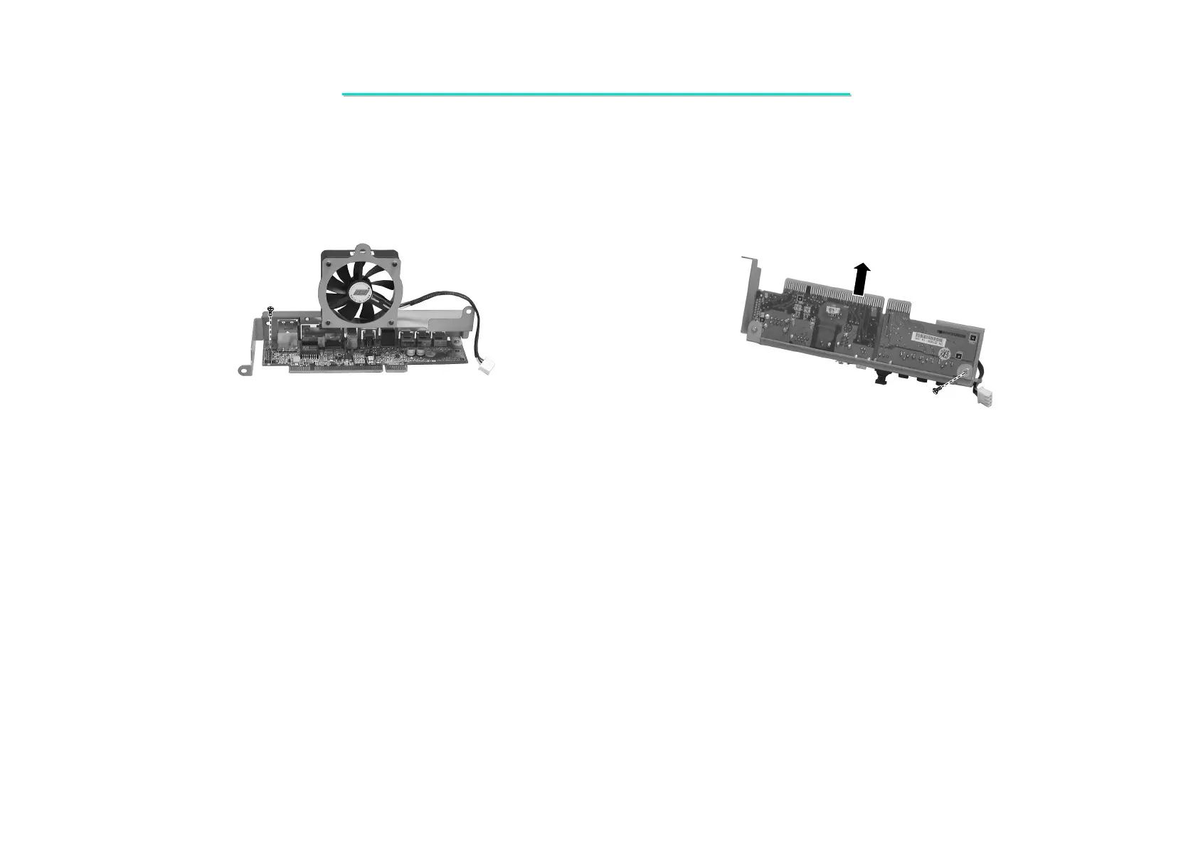
4. Remove one screw on the I/O board. (Figure 2-9)
5. Remove one screw on the bottom of the I/O board. Then lift it up. (Figure 2-10)
Figure 2-9 Remove one screw Figure 2-10 Remove one screw
Reassembly
1. Fit the I/O board and secure with two screws.
2. Reconnect the the Modem card’s wire () and fan’s power cord of the I/O board ().
3. Fit the I/O board and secure with four screws.
4. Replace the heatsink; housing shielding and CPU cover. (See section 2.2.2 reassembly)