5Functions set with parameters
Movement parameter 5-441
User area AREA*P2
* is 1 to 32
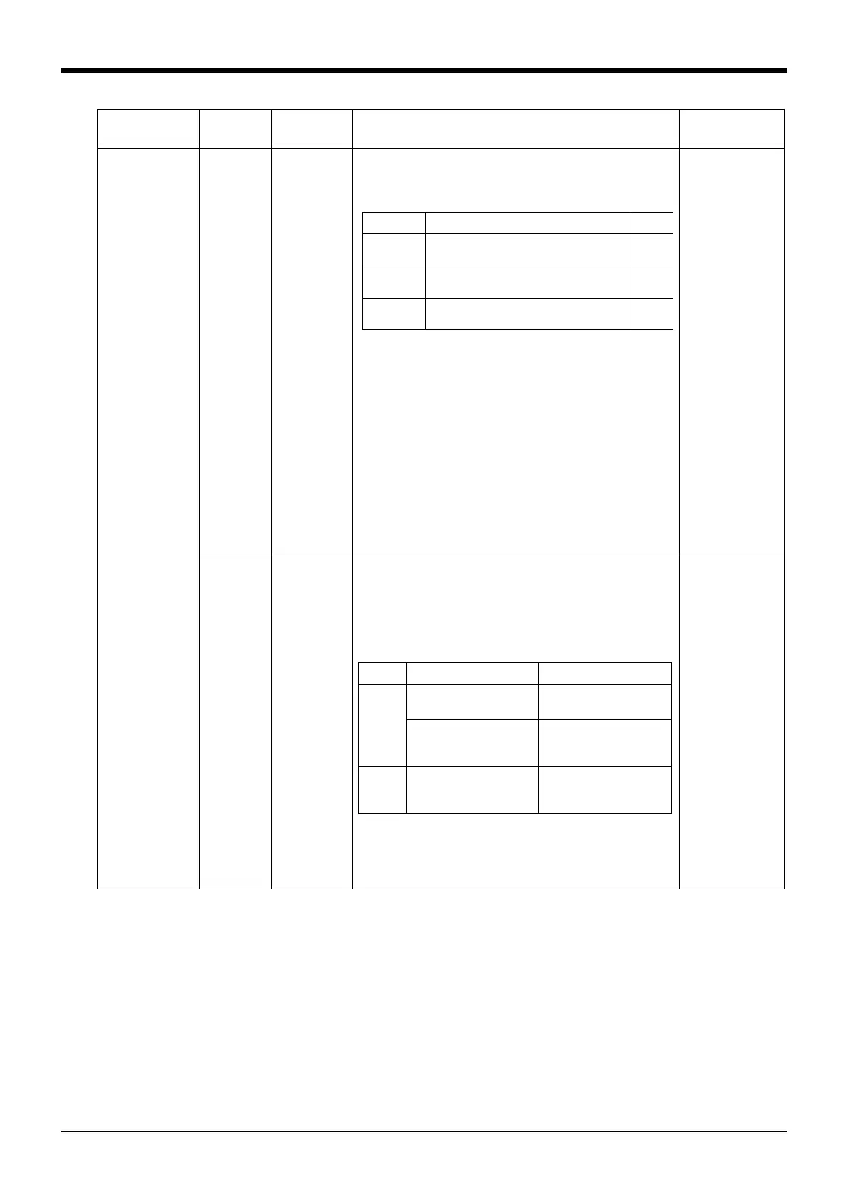
Real value 8 Designates position coordinates of the diagonal point 2 of the
user-defined area * and coordinates of posture data/additional
axes. Definitions are given, starting with the 1st element, to X, Y,
Z, A, B, C, L1, and L2 in the order listed.
<NOTES>
*Specify values in the coordinate system which was designated
by AREA*CS.
*If a posture check is not to be made, set A, B and C coordinates
to +360.
*If additional axes are used, specify elements L1 and L2.
*In regard to elements X, Y, Z, L1 and L2, defined area remains
unchanged if parameter interchange is made to AREA*P1.
(X,Y,Z,A,B,C,L1,L2)
= 0.0, 0.0, 0.0,
-360.0, -360.0,
-360.0, 0, 0
AREA*ME
* is 1 to 32
Integer 1 Designate the mechanism No. for which the user-defined area*
is to be validated.
The mechanism No. is 1 to 3, but normally 1 is set.
0: Invalid (Don't do the area check)
1: Mechanism 1 (usually set up)
2: Mechanism 2
3: Mechanism 3
0
AREA*AT
* is 1 to 32
Integer
1Outside of the
area
Specify desired behavior when the robot enters the user-defined
area.
0: Invalid (This function will be invalid)
1: In-zone signal output (The dedicated output and the status
variable output)
2: Error output.
<Details of the setting>
<NOTES>
If error output is opted for, a check is performed only in the posi-
tion area, ignoring the posture area and additional axis area.
0(Invalid)
Parameter
Parameter
name
No. of arrays
No. of characters
Details explanation Factory setting
Item Details Unit
X, Y, Z
elements
Specify position coordinates of the
diagonal point 2.
mm
A, B, C
elements
Specify posture area. deg
L1, L2
elements
Specify additional axis area. mm,
deg
*1: Set up the signal number of the dedicated I/O by USRAREA
*2: System status variable (M_Uar32, M_Uar)
Setting Inside of the area Outside of the area
Signal
output
The dedicated output
signal ON (*1)
The dedicated output
signal OFF
Turn on the correspon-
dence bit of the status
variable. (*2)
Turn off the correspon-
dence bit of the status
variable.
Error
output
The stop by the error
output (H2090 error
occurrence)
-
 Loading...